Camera And ChArUco Keep The Skew Out Of Your 3D Prints

Do you or a loved one suffer from distorted 3D prints? Does your laser cutter produce parallelograms instead of rectangles? If so, you might be suffering from CNC skew miscalibration, and you could be entitled to significant compensation for your pain and suffering. Or, in the reality-based world, you could simply fix the problem yourself with this machine-vision skew correction system and get back to work.

If you want to putĀ [Marius Wachtler]’s solution to work for you, it’s probably best to review his earlier work on pressure-advance correction. The tool-mounted endoscopic camera he used in that project is key to this one, but rather than monitoring a test print for optimum pressure settings, he’s using it to detect minor differences in the X-Y feed rates, which can turn what’s supposed to be a 90-degree angle into something else.

The key to detecting these problems is the so-called ChArUco board, which is a hybrid of a standard chess board pattern with ArUco markers added to the white squares. ArUco markers are a little like 2D barcodes in that they encode an identifier in an array of black and white pixels. [Marius] provides a PDF of a ChArUco that can be printed and pasted to a board, along with a skew correction program that analyzes the ChArUco pattern and produces Klipper commands to adjust for any skew detected in the X-Y plane. The video below goes over the basics.

For as clever and useful as ChArUco patterns seem to be, we’re surprised we haven’t seen them used for more than this CNC toolpath visualization project (although we do see the occasional appearance of ArUco). We wonder what other applications there might be for these boards. OpenCV supports it, so let us know what you come up with.

Continue reading “Camera And ChArUco Keep The Skew Out Of Your 3D Prints”

CNC Toolpath Visualisation With OpenCV

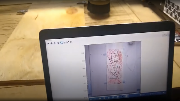
[Tony Liechty] has been having a few issues getting into CNC machining — starting with a simple router, he’s tripped over the usual beginners’ problems, you know, things like alignment of the design to the workpiece shape, axis clipping and workpiece/clamp collisions. He did the decent hacker thing, and turned to some other technologies to help out, and came up with a rather neat way of using machine vision with OpenCV to help preview the toolpath against an image of the workpiece in-situ (video, embedded below.)

ChArUco (a combined chessboard and ArUco marker pattern) boards taped to the machine rails were used to give OpenCV a reference of where points in space are with respect to the pattern field, enabling identification of pixel locations within the image of the rails. A homography transformation is then used to link the two side references to an image of the workpiece. This transformation allows the system to determine the physical location of any pixel from the workpiece image, which can then be overlaid with an image of the desired toolpath. Feedback from the user would then enable adjustment of the path, such as shifts, or rotates to be effected in order to counter any issue that can be seen. The reduction of ‘silly’ clamping, positioning and other such issues, means less time wasted and fewer materials in scrap bin, and that can only be a good thing.

[Tony] says this code and setup is just a demo of the concept, but such ‘rough’ code could well be the start of something great, we shall see. Checkout the realWorldGcodeSender GitHub if you want to play along at home!

We’ve seen a few uses of OpenCV for assisting with CNC applications, like this cool you draw it, i’ll cut it hack, and this method for using machine vision to zero-in a CNC mill onto the centre of a large hole.

Continue reading “CNC Toolpath Visualisation With OpenCV”