Automatic, Custom Eagle Schematics

sch

It’s a simple fact that for every circuit you design, someone else has done it before. If you’re working on a high altitude balloon project, there’s already a project out there with a microcontroller, barometric pressure sensor, and an SD card somewhere out there in a corner of the Internet. Google will only help so much if you want to copy these previous builds, which led [Ben] to come up with a better solution. He took dozens of building blocks for basic digital projects and put them all into one really great interface called HackEDA.

The premise is simple: most electronic projects are just electronic Lego. You connect your microcontroller to a sensor, add in a battery, throw in a few caps and resistors for good measure, and hopefully everything will work. HackEDA takes all those basic building blocks – microcontrollers, power sources, and sensors – and creates a custom Eagle schematic with all the parts your project needs

HackEDA is still very much in beta, so there aren’t a whole lot of building blocks to choose from. That said, being able to generate an Eagle schematic with all the parts necessary for your next project is a boon. With this, all you need for a final circuit board is to create a new board file, hit the autorouter, and spend a half hour fixing whatever mess the autorouter made.

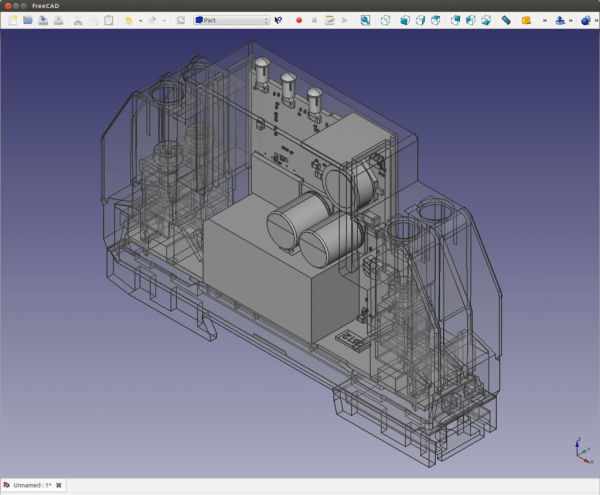
Script Lets You Import Eagle Boards For Use In FreeCAD

eagle-designs-imported-for-freecad

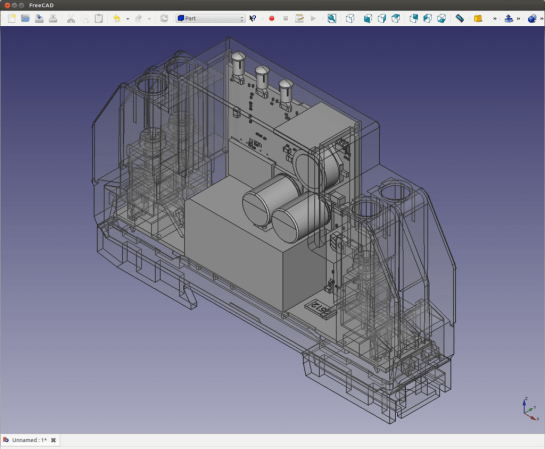
[Christian Aurich] wanted to use his Eagle CAD circuit board design in a proper CAD program in order to design enclosures. There are already a few options along these lines, but they didn’t quite fit his needs so he developed a script to import Eagle boards into FreeCAD. The script is packaged as a python macro for FreeCAD.

In describing the shortcomings of what’s already out there [Christian] does mention the use of EagleUp to model boards in Google SketchUp. But he feels the way the data is produced by SketchUp makes these models work well with 3D printing, but says they’re not easy to use with mechanical design CAD software. He also feels that the photo-realistic renderings are useless when developing enclosures.

It’s worth mentioning that this approach is only possible because CadSoft’s migration to XML makes it dead simple to get at the data.

Renaming Parts In Eagle CAD By Editing The XML Directly

eagle-xml-find-and-replace-script

There’s a lot of ways to burn up your time when designing PCBs, but renaming components can be one of the most frustrating. [Joe Pinzone] wrote in with his solution to the problem. Instead of hunting for each part on the schematic to change them one at a time, he makes a list of the substitutions and then uses a script to make all the changes in the XML files. He didn’t publish a post about his work, but you’ll find the source code he wrote embedded after the break.

The straw that finally broke the camel’s back was a project that included about two hundred components which didn’t seem to have a naming order that made any sense with the actual values of the components. The script is written in C++ (for Windows but [Joe] says this should be easily ported to other systems as well). To use it he creates a CSV file with the current component names in the first column. He then goes through and types what he wants for the new name in the second column. This CSV, along with the BRD and SCH files are then given as inputs for the script (through selecting them all and dragging to the script or as CLI arguments) and it automatically makes the changes.

Of course this is only possible because Cadsoft transitioned to using XML files in Eagle 6.

Continue reading “Renaming Parts In Eagle CAD By Editing The XML Directly”

Custom Circuit Drives A Small Round CRT Display

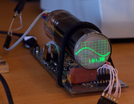
[Svofski’s] latest hack seeks to do no more than look cool on his desk. We’d say mission accomplished. He doesn’t even need anyone around to be proud of the small round CRT display unit he put together. Just having it hum away next to him will be more than enough to keep him going when regular work gets a bit tedious.

One of the biggest challenges when working with a cathode ray tube is the supply. He compares the requirements with that of Nixie tubes, and this is quite a bit more challenging since he wants to generate the 750V from a 12V DC source. To pull it off he hand wound his own transformer. There are two secondary coils, one for the cathode heater and the other as the supply. You can see a brief clip of the unit in action after the break.

Take note of the PCB section of his writeup. He took a meandering route through several different software packages before printing the board. It started with Eagle, moved to freerouting.net, which produced a Specctra file that he converted to gEDA using a Python script.

Continue reading “Custom Circuit Drives A Small Round CRT Display”

Designing A Quadcopter Brain PCB

When working on his quadcopter project [Matt] decided it would be best to build a robust controller for the device. He had never sent off a PCB design for fabrication, but took the plunge and ended up with a compact and reliable PCB on the first try.

One of the first things that comes to mind when we hear about quadcopter controllers are the feedback sensors. The accelerometers which are used for these projects generally come in a DFN or QFN package. This means there are no legs. Instead the chip has pads on the bottom of the package making it a lot more difficult to solder. [Matt] side-stepped this issue by using an IMU board which already has the sensors in place and offered a 0.1″ SIL pin header to use as an interface. This is simple to roll into the design, along with all of the other connectors for motor control, power, etc. He grabbed a copy of Eagle Lite to do the layout, and used OSH Park to get the boards fabricated. He was surprised that everything worked on the first try. Thanks to his planning it fits inside of a plastic food container where it should be able to ride out most minor crashes with ease.

A Guide For Laying Out 4+ Layer PCBs

Learning to lay out a printed circuit board takes some time. But after you’ve churned out a few it’s really pretty easy. If you find yourself at that point it may be time to learn about more complicated board fabrication. We think a good primer is this multi-layer PCB layout guide which [Rik te Winkel] recently put together. It’s one of the results of his internship experience.

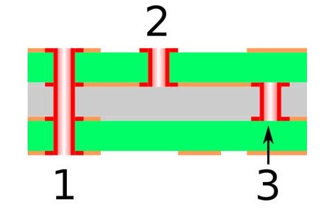
One of the major differences with boards that have more than two layers is the ability to alter what layers are actually connected by vias. Vias are plated holes through the substrate that connect different layers of copper. In the case of a 2-layer board these just go right through and connect the top to the bottom. But as you can see above, there are additional choices when it comes to multi-layer boards. #1 is a through via connecting all of the layers. #2 is a blind via; it stops part way through the board. And #3 is a buried via; it connects internal layers but cannot be seen from either side.

The guide is aimed at Eagle CAD. To use more than two layers you’ll have to purchase a license. But we think the concepts can easily be translated to other PCB layout software like Kicad.

This Is Not Real: Lifelike Renderings From Eagle Files

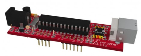
Look at it. Just look at it! This board is a lie. It doesn’t exist (at least not what’s seen in the image here). Instead this is a lifelike rendering made from Eagle CAD files.

We’ve already seen that it is rather easy to pull Eagle CAD files into Google SketchUp thanks to the EagleUp package. You’ll get a 3D model that looks quite nice but it’s hardly photo-realistic. This process starts exactly the same way. But you’re going to want to process the SketchUp file one more time.

A program called Kerkythea does this for you. It’s an open source project aimed at producing realistic renderings. It has a plugin which will process any SketchUp model and apply the textures and shadings that look so wonderful in the image above. It’s not a one-click process, but reminds us of the mountain of options you’d find in a program like Blender3D. You’ll need to map out settings for each different material you’d like to map, but the guides found at the link above do a good job of showing how it’s done.