30-Year-Old Macintosh SE/30 Gets A Brand New Logic Board

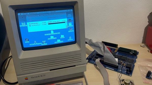
Some time ago, [Bolle] got the idea to redraw the Macintosh SE/30 schematics in Eagle. Progress was initially slow, but over the past month (and with some prodding and assistance from fellow forum frequenter [GeekDot]), he’s taken things a step further by creating a fully functional replacement Macintosh SE/30 logic board PCB.

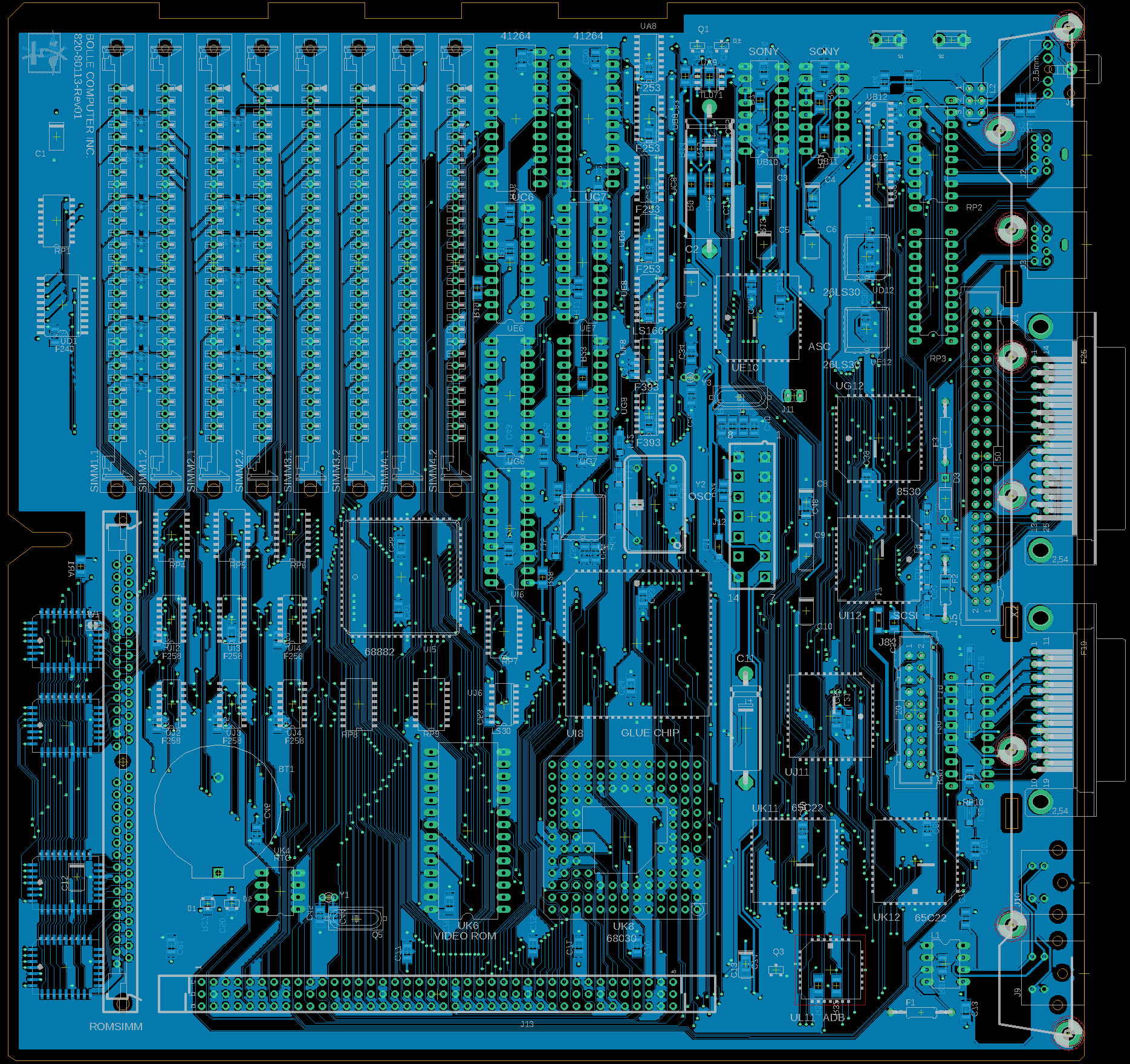
By using the available schematics, the project didn’t even require much reverse engineering. Though he plans for more modernization in later iterations, this design is largely faithful to the original components and layout, ensuring that it is at least basically functional. He did update the real time clock battery to a CR2032 and, as a benefit of redrawing all the traces, he was able to use a 4-layer PCB in place of the costly 6-layer from Apple’s design.

The board came back from fabrication looking beautiful in blue; and, once he had it soldered up and plugged in, the old Mac booted on the very first try! A copy-paste mistake with the SCSI footprints led to some jumper wire bodging in order to get the hard drive working, but that problem has already been fixed in the next revision. And, otherwise, he’s seen no differences from the original after a few hours of runtime.

Recreating old Macintosh logic boards almost seems like its own hobby these days. With the design and fabrication capabilities now accessible to hobbyists, even projects that were once considered professional work are in reach. If you’re interested in making your own PCB designs, there are many resources available to help you get started. Alternatively, we have seen other ways to modernize your classic Macs.

[Thanks to techknight for the tip!]

Friday Hack Chat: Eagle One Year Later

Way back in June of 2016, Autodesk acquired Cadsoft, and with it EagleCAD, the popular PCB design software. There were plans for some features that should have been in Eagle two decades ago, and right now Autodesk is rolling out an impressive list of features that include UX improvements, integration with MCAD and Fusion360, and push and shove routing.

Six months into the new age of Eagle, Autodesk announced they would be changing their licensing models to a subscription service. Where you could pay less than $100 once and hold onto version 6.0 forever, now you’re required to pay $15 every month for your copy of Eagle. Yes, there’s still a free, educational version, but this change to a subscription model caused much consternation in the community when announced.

For this week’s Hack Chat, we’re going to be talking about Eagle, one year in. Our guest for this Hack Chat is Matt Berggren, director of Autodesk Circuits, hardware engineer, and technologist that has been working on bringing electronic design to everyone. We’ll be asking Matt all about Eagle, with questions including:

  • What new features are in the latest edition of Eagle?
  • What’s on the Eagle wishlist?
  • What technical challenges arise when designing new features?
  • Where can a beginner find resources for designing PCBs in Eagle?

Join the chat to hear about new features in Eagle, how things are holding up for Eagle under new ownership, and how exactly the new subscription model for Eagle is going. We’re looking for questions from the community, so if you have a question for Matt or the rest of the Eagle team, put it on the Hack Chat event page.

If you’re wondering about how Altium and KiCad are holding up, or have any questions about these PCB design tools, don’t worry: we’re going to have Hack Chats with these engineers in the new year.

join-hack-chat

Our Hack Chats are live community events on the Hackaday.io Hack Chat group messaging. This Hack Chat is going down on noon, PST, Friday, December 15th. Time Zones got you down? Here’s a handy count down timer!

Click that speech bubble to the left, and you’ll be taken directly to the Hack Chat group on Hackaday.io.

You don’t have to wait until Friday; join whenever you want and you can see what the community is talking about.

Christmas Lights Done The Hard Way

It’s that time of the year again when you gotta start worrying if you’ve been naughty enough to not receive any gifts. Hopefully, Blinky Lights will appease St. Nick. Grab a strip of RGB LEDs, hook them up to an Arduino and a Power supply, slap on some code, and Bob’s your Uncle. But if you want to retain your hacker cred, you best do it the hard way. Which is what [roddersblog] did while building his Christmas Starburst LED Stars this year — and bonus points for being early to the party.

christmas-lights-the-hard-way
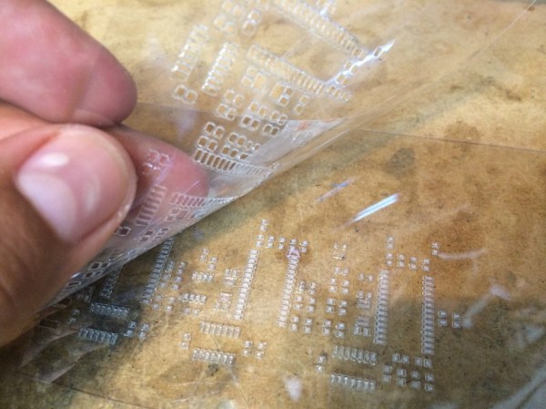
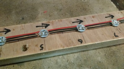
For starters, he got panels (as in PCB panels) of WS2812 boards from eBay. The advantage is it lets you choose your own pitch and strand length. The flip side is, you need to de-panel each board, mount it in a jig, and then solder three lengths of hook up wire to each LED. He planned for an eight sided star with ten LED’s each. And he built three of them. So the wiring was, substantial, to say the least. And he had to deal with silicone sealant that refused to cure and harden. But nothing that some grit and determination couldn’t fix.

For control, he choose the PIC16F1509 microcontroller. This family has a feature that PIC calls the “Configurable Logic Cell” and this Application Note describes how to use CLC to interface the PIC to a WS2811. He noticed processing delays due to C code overheads that caused him some grief. After some experimentation, he re-wrote the entire program in assembly which produced satisfactory results. You can check out his code on the GitHub repository.

Also well worth a look, he’s got a few tricks up his sleeve to improve the quality of his home-brew PCB’s. He’s built his own UV exposure unit with timer, which is an interesting project in itself. The layout is designed in Eagle, with a flood fill to minimize the amount of copper required to be etched away. He takes a laser print of the layout, applies vegetable oil to the paper to make it more translucent to UV, and doubles up the prints to get a nice contrast.

Once the sensitized board has been exposed in the UV unit, he uses a weak but fresh and warm solution of Sodium Hydroxide as a developer to remove the unexposed UV photo-resist. To etch the board, he uses standard Feric Chloride solution, which is kept warm using an aquarium heater, while an aquarium air-pump is used to agitate the solution. He also describes how he fabricates double sided boards using the same technique. The end result is quite satisfying – check out the video after the break.

Continue reading “Christmas Lights Done The Hard Way”

Extending EagleCAD With Python

eagle
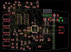
Although it’s derided for not being open source, EagleCAD is an extremely popular piece of schematic and PCB layout software. Most of the popularity is probably due to the incredible amount of part libraries – it’s certainly not the features Eagle has to offer or its horrible scripting capabilities. [Rob] had enough of the lack of good scripting support in Eagle, so he’s been spending his time making Eagle’s ULP work with Python. He’s only been at it a short time, but already it’s much more usable than the usual Eagle scripts.

Below you can check out a pair of videos of [Rob]’s Python tools for Eagle in action. The first video goes through aligning a few symbols and creating a board outline (with proper curves!) from a DXF file. The second video shows exactly how valuable these tools are when laying out a board: imagine hundreds of LEDs and resistors automatically aligned to each other with a single click of a mouse. Beautiful.

All the PyEagle stuff is available on [Rob]’s github, with a DXF importer, group manager, and alignment tool included. Now that everything’s Python, it’s easy to build your own tools without relying on Eagle’s odd ULP language.

Continue reading “Extending EagleCAD With Python”

Solder Stencil

How To Laser Cut Mylar Solder Stencils

When you think about the difficulties of working with surface mount components, the first thing that often comes to mind is trying to solder those tiny little parts. Instead of soldering those parts by hand, you can actually apply solder paste to the pads and place all of the components on at once. You can then heat up the entire board so all of the parts are soldered simultaneously. It sounds so much easier! The only problem is you then need a solder stencil. You somehow have to get a thin sheet of material that has a perfectly sized hole where all of your solder pads are. It’s not exactly trivial to cut them out by hand.

[Juan] recently learned a new trick to make cutting solder stencils a less painful process. He uses a laser cutter to cut Mylar sheets into stencils. [Juan] appears to be using EagleCAD and Express PCB. Both tools are available for free to hobbyists. The first step in the process is to export the top and bottom cream layers from your CAD software.

The next step is to shrink the size of the solder pads just a little bit. This is to compensate for the inevitable melting that will be caused by the heat from the laser. Without this step, the pads will likely end up a little bit too big. If your CAD software exports the files as gerbers, [Juan] explains how to re-size the pads using ViewMate. If they are exported as DXF files, he explains how to scale them using AutoCAD. The re-sized file is then exported as a PDF.

[Juan’s] trick is to actually cut two pieces of 7mil Mylar at the same time. The laser must be calibrated to cut all the way through the top sheet, but only part way into the bottom piece. The laser ends up slightly melting the edges of the little cut out squares. These then get stuck to the bottom Mylar sheet. When you are all done cutting, you can simply pull the sheets apart and end up with one perfect solder stencil and one scrap piece. [Juan] used a Full Spectrum 120W laser cutter at Dallas Makerspace. If you happen to have this same machine, he actually included all of the laser settings on his site.

Stylish OLED Watch Uses Accelerometer Instead Of Buttons

A few days ago [Andrew] contacted us to offer his help for the design of the mooltipass project case. While introducing himself, he casually mentioned his OLED watch that you can see above.

The watch is based on the low-power MSP430F microcontroller from Texas Instruments. It can consume as little as 1.5uA while maintaining a real-time clock and monitoring interrupts. It also uses ferroelectric RAM, which doesn’t need any power to retain its memory contents. That means there’s no need to set the time again if you remove the CR2016 battery that powers the watch.

[Andrew] chose an 0.96″ OLED display that only consumes up to 7mA. He also included an accelerometer that allows him to interact with the watch through its single and double tap detecting feature. He modeled his PCB using EagleCAD and the whole assembly using Sketchup. Most of the components were soldered in his reflow (toaster) oven. The final result is a mere 8.8mm thick and looks very professional in our opinion.

Persistence Of Vision Planetary Map

POV planetary map

Looking at the looping GIF above you’re probably thinking, oh, another hard drive POV setup… Well… Not quite.

This is one of [Dev’s] latest projects, and it is a planetary map that shows the angular positions of all 8 of the major celestial bodies from any given date between 1800 and 2050. It’s also capable of showing analogue clock hands, the phases of the moon, and other simple graphics.

The main unit is a hard disk, but [Dev] milled off many of the features on it to give it a more exposed, purpose-built look. He designed the LED bearing PCB from scratch using EagleCAD, which sits on the back of the drive, with the spindle poking through. It has 8 rings of 5 surface mounted LEDs, which shine through opaque plastic diffuser rings that he printed using Shapeways — they feature small recesses to fit snugly on the board over the LEDs. On the top level is a 1mm thick black disc of some unknown material that [Dev] had sitting around, which now has 8 holes machined into it in the exact position of the LEDs.

A Cortex-M0 drives the LEDs using an LPCXpresso board which allows the LEDs to sit across only one byte of a hardware I/O port. On the software end, each rotation of the disk is segmented into three hundred and sixty 1 degree slices. This system allows him to achieve a circular resolution of 8×360 pixels at 25 frames per second. Not bad for a persistence of vision device!

Stick around after the break to see the rather entertaining demo video of the device.

Continue reading “Persistence Of Vision Planetary Map”