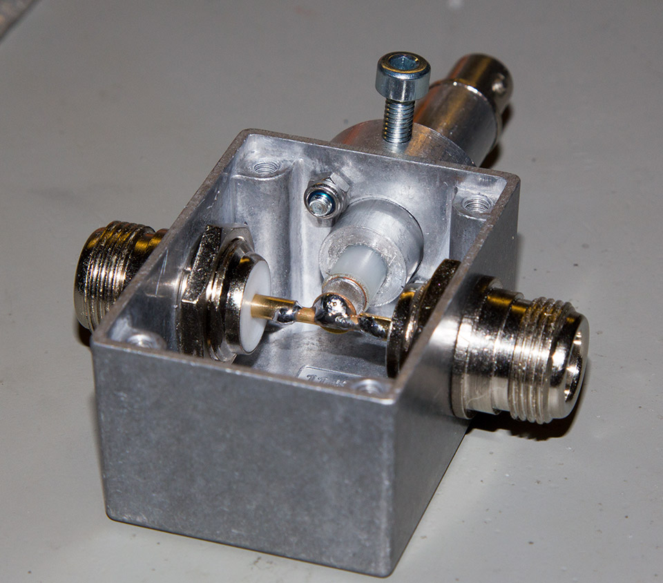
One of [Brian]’s hobbies is Amateur Ham radio, in which it is usually required to check that the transmitted signals are within specifications. As it isn’t safe to connect the radio’s output directly to measuring equipment due to the high voltages involved, [Brian] made his own dedicated RF signal sampler. It works by using capacitive coupling between the signal you wish to sample and a high impedance output. The latter can then safely be connected to an oscilloscope or spectrum analyzer for monitoring.
In the picture you see above, the air gap between the core signal conductor and the output plays the role of a capacitor. By adjusting its length you can therefore vary the output signal’s voltage range. The sampler is built using a die-cast aluminium enclosure which is 52x38x27mm. As you may have guessed, due to the case geometry the output attenuation will depend on the signal’s frequency. [Brian] tested the unit using a 30MHz signal generator and printed this frequency attenuation graph while also varying the air gap.


