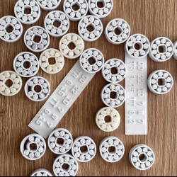
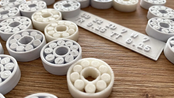
3D printing bearings with an FDM printer can be an iffy endeavor, but it doesn’t have to be that way. [Matvey Kukuy]’s Ultimate 608 Bearing with Calibration Kit is everything you’ll need to dial in and print functional 608-style print-in-place bearings on your 3D printer.

[Matvey] found that there are two key tolerances to get right. And by “get right” he means “empirically determine which works best with your filament and printer”. But don’t worry, there’s no need to get into CAD work to make that happen. [Matvey] has exported a staggering 64 slightly different calibration models (and their matching production versions) along with a printable testing tool. With the help of a step-by-step process that resembles a sort of binary search, one can take the Goldilocks approach to find just the right model for one’s filament and printer in a minimum of steps.
There’s one more tip as well: [Matvey] says that once you determine the best model to use, don’t fill the print bed with copies, unless you want a bed full of possibly non-working bearings! Why is this? A 3D printer prints a bed full of objects slightly differently than it prints a single one, and since the margin for error on the perfectly-selected bearing is so small, that can be enough to keep it from working. To print more than one bearing at a time, position them far from each other and use something like PrusaSlicer’s sequential printing, which is an option to print each object completely before starting the next one.
[Matvey]’s own best results came from printing with PLA at a layer height of 0.16 mm. He also used grease in the bearing to improve performance and extend its life. He doesn’t specify what kind of grease he used, but we’d recommend a plastic-safe grease like PTFE-based Super Lube.
Have you used 3D printed bearings in a project? Would [Matvey]’s design be helpful to you? Let us know all about it in the comments.


