
Many years ago, audio equipment came with a tone control, a simple RC filter that would cut or boost the bass to taste. As time passed, this was split into two controls for bass and treble, and then finally into three for bass, mid, and treble. When audiophile fashion shifted towards graphic equalisers, these tone controls were rebranded as “3-band graphic equalisers”, a misleading term if ever we heard one. [Gabriel Dantas] designed one of these circuits, and unlike the simple passive networks found on cheap music centres of old, he’s doing a proper job with active filters.
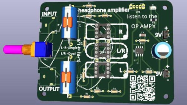
The write-up is worth a read even if you are not in the market for a fancy tone control, for the basic primer it gives on designing an audio filter. The design contains, as you might expect, a low-pass, a bandpass, and a high-pass filter. These are built around TL072 FET-input op-amps, and an LM386 output stage is added to drive headphones.
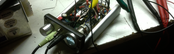
The final project is built on a home-made PCB, complete with mains power supply. Audiophiles might demand more exotic parts, but we’re guessing that even with these proletarian components it will still sound pretty good. Probably better than the headphone amplifier featured in a recent project from a Hackaday writer, at least. There’s a build video, below the break.


 Since she was going with an oscilloscope style vector scan rather than the raster scan the screen electronics were originally designed for, [ErikaFluff] had to create her own horizontal and vertical deflection circuits. Horizontal scan is created by a 555 timer generating a sawtooth wave at 75 Hz. Vertical deflection is via an LM386 driving a hand wound impedance matching transformer. The high voltage flyback transformer and its associated driver circuit were kept from the original CRT, though repackaged to make them as small as possible.


