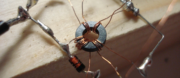
We’ve seen NAND and NOR logic gates – the building blocks of everything digital – made out of everything from marbles to Minecraft redstone. [kos] has outdone himself this time with a logic circuit we’ve never seen before. It’s based on magnets and induction, making a NOR gate out of nothing but a ferrite core, some wire, and a diode.
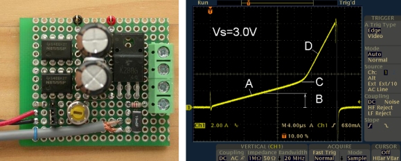
The theory of operations for this magnetic NOR gate goes as follows: If two of the input windings around the core have current passing in different directions, the fields cancel out. This could either be done by positive or negative voltages, or by simply changing the phase of the winding. To keep things simple, [kos] chose the latter. The truth table for a simple two-input, one-output gate gets pretty complicated (or exceedingly cool if you’d like to build a trinary computer), so to get absolute values of 1 and 0, a separate ‘clock’ winding was also added to the core.
One thing to note about [kos]’ gate is its innovation on techniques described in the relevant literature. Previously, these kinds of magnetic gates were built with square ferrites, while this version can work with any magnetic core.
While this isn’t a very practical approach towards building anything more complex than a memory cell, it is an exercise of what could have been in an alternate universe where tube technology and the transistor just didn’t happen.