Making Laser Adjustments With An SNES Gamepad

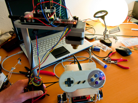
Gaming has infiltrated everything around us. It seems that any time a control interface is needed, the first thought to many current hacker’s minds are the familiar controls from the video games we grew up with. In this example, [eljaywasi] needed a way to control the wavelength of light coming out of a laser. We don’t know exactly how he’s actually changing the wavelength, but we do know he’s using an SNES gamepad as his interface. You can see a red and a blue LED located on the front of the pad, so it may be that two buttons would have sufficed. We don’t care, we like the SNES pad better.

Tilt Sensor Toy Is Simple And Mesmerizing

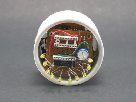
[Eiki] found himself in need of a project for his “simple machines” class. Another project had brought him in contact with some relatively cheap MEMS accelerometers and gyroscopes.  He had the idea to create a simple tilt sensor based circuit that would light whatever LED was at the bottom.

He’s using an Analog Devices ADXL202E accelerometer chip to sense tilt and an  LM3914 bar-graph driver to light the displays. He’s taking the voltage-proportional-to-accelleration output of the accelerometer, filtering it through a capacitor, then feeding it to the bar-graph driver. It may not be the most technically difficult project, but the result is mesmerizing and elegant.

An Excellent Introduction To Transmission Lines

[Bertho] sent in a great tutorial on terminating transmission lines. If you’ve ever tried to send a high frequency signal a long way down a wire, you know the problems that can crop up due to electronic strangeness. Luckily [Bertho]’s tutorial explains just about everything, from where and when to terminate a cable and why signals get screwed up in long wires.

[Bertho] begins his lesson by taking two oscilloscopes and 20 m of CAT5 cable with the twisted pairs wired in series to make an 80 meter long transmission line. A ~100kHz square wave was sent down the cable after being displayed on the first oscilloscope, and picked up on the other end by the second oscilloscope. It’s a great way to show the changes in a signal over a long cable run, and how small changes in the circuit (just adding a simple resistor) can affect the signal coming out of a cable.

It’s a great post that demystifies the strange electrical gremlins that pop up when you’re running a length of wire. Great job, [Bertho].

Metal Detection Using An Inductor Instead Of A Clock Crystal.

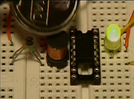
This project from a few years back is an interesting take on a metal detector. Instead of building a detection circuit, [Bruno Gavand] replaced the external clock crystal with an inductor. Here you can see the inductor coil next to the PIC 12F683. You can see two components jumping from one breadboard to the other. These are smoothing capacitors on the inductor lines.

The watchdog timer for the chip is run by the internal RC oscillator. When the external crystal receives a pulse due to metal inducing a current in the coil, the value of the watchdog timer is compared to it. This data is filtered and if the proper parameters are present the green LED blinks. This is bicolor LED. If the inductor circuit is functioning properly it will blink red at power up. [Bruno] says that results will vary based on that inductor so you may need to try a few to get the calibration light to blink.

We’re thinking this would make a simple stud finder (by detecting where the nails/screws are in the wall). Check out the demo after the break, then let us know what you would use this for by leaving a comment.

Continue reading “Metal Detection Using An Inductor Instead Of A Clock Crystal.”

Light Programming For A Clock

+

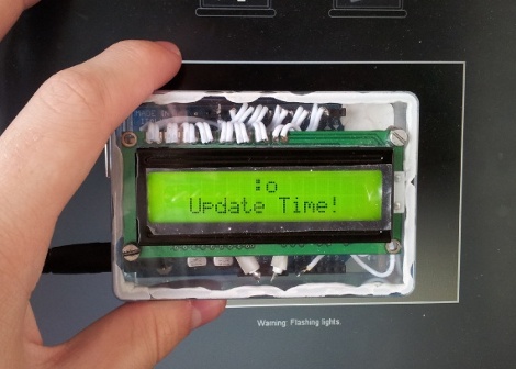
So at first glance we were thinking there wasn’t much special about this clock. It’s based on an Arduino and displays the time using a character LCD screen. But then we realized that there’s no battery-backed RTC and no buttons. How the heck do you set the time on this thing? [Mossblaser] is using a light programmer to set the time using a computer screen.

We’ve tried nearly the same data transfer technique before, using a white and black flashing computer screen to push Manchester encoding to a light dependent resistor. We were met with limited success, but you can see that [Mossblaser’s] rig is much more reliable and we think there’s a few reasons behind this. First, he’s only sending five bits per seconds, a very slow speed when it comes to digital transmissions. This helps to make up for slow LCD screen refresh. Also, the LDR is surrounded by material on the back of the case that will help to block out ambient light. And finally, he’s using a smaller part of the screen instead of flashing the whole thing. This may result in more accurate timing. You’ve got to admit, this is pretty slick!

Continue reading “Light Programming For A Clock”

There’s More Than Meets The Eye To This Robot Car

This is a robot that any Transformers enthusiast will love. Sure, the car looks just a bit boxy, but you’ll forget all about that when you see it unfold into a bipedal robot (translated). [Zak Sawa] is responsible for the creation. He pull off the build using 22 servo motors which let the car transform, and provide the somewhat awkward ability to walk. Fold it back up again and the car can drive away. In other words, here’s the Transformers toy that you always wanted; radio controled and it actually works!

This is the result of about four years of work. Apparently it’s the eighth iteration, and a note on the video after the break teases a ninth version on the way. It’s not just the robot that looks great, check out the carrying case that houses it for storage.

Continue reading “There’s More Than Meets The Eye To This Robot Car”

RC Car Controller And Receiver Replacement

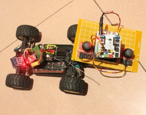
This radio controlled car controller replacement is a great project to try some new things with that fancy hardware you’ve got sitting around. The hack comes in two parts, the receiver and the transmitter. They’re communicating via Bluetooth so if you only want to build one side of the hardware you should be able to make most Bluetooth devices work as the other. For instance, build the receiver for the car and control it with a Wii remote. Or use the controller to play emulator games on an Android phone.

Both pieces are Arduino based. The controller makes use of a Freeduino with a Bluetooth shield as well as a pair of analog stick breakout boards. The car side of things uses a Bluetooth Bee (a Bluetooth module that is pin compatible with an Xbee socket) and an Arduino pro. Once the hardware bits are assembled, it takes very little code to get the system up and running. Join us after the break for a quick clip of the car in action.

Continue reading “RC Car Controller And Receiver Replacement”