Op Amp Challenge: An Ultra-Cheap PH Sensor Amplifier

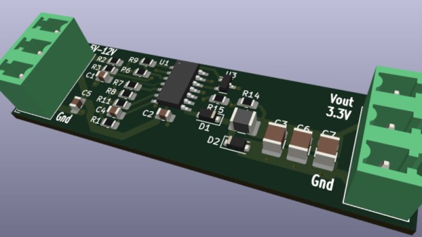
It’s rare in 2023 for an instrument to be entirely analog, instead it’s more normal for a front-end to feed the analog-to-digital converter (ADC) in a microcontroller. Typically the front-end will do the job of transforming whatever the output range of the sensor is, and present it to the microcontroller in whatever range it accepts. [David] had exactly this problem with a pH sensor, and rather than buy an expensive module to do the job he designed his own.

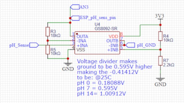
The sensor in question produces a relatively tiny voltage of -0.414 to +0.414 volts, and requires a very high input impedance. A FET input op-amp is selected, with the ground of the sensor shifted upwards into the positive range by a voltage divider. This then feeds a second op-amp that amplifies the resulting DC voltage for the microcontroller input.

This circuit is an especially simple op-amp application, and is a typical one for a sensor interface where a DC voltage needs to be brought into range of a microcontroller. If you’re not used to op-amp circuits then take a look, this type of analogue circuit is not difficult and might just save your butt some time.

Want to know more about simple op-amp circuits? Have we got the video for you!

Op Amp Challenge: An Op-Amp Buck Regulator

Switching regulators have delivered such convenience and efficiency compared to their linear siblings, that it’s now becoming rare to see an old-style three-terminal regulator. Modern designs have integrated to such an extent that for many of us the inner workings remain something of a mystery. It’s still possible to make switching regulators from first principles though, which is what [Aaron Lager] has done by designing a buck regulator from a quad op-amp IC,

It’s an entry in our Op Amp Challenge and it appears to be a work in progress, but the design is solid enough. We’re no fans of the schematic style of representing an op-amp chip as a rectangle rather than individual op-amps, but it’s simply a PWM generator with a final op-amp used as a driver for the usual diode-inductor-capacitor network. We’re guessing that the op-amp driver won’t make this the most powerful of switchers, but in this case that’s hardly the point. Build this if you’re interested in taking an op-amp out of its normal sphere, or if you’re interested in the workings of a buck converter.

Need more in the way of switching regulators from first principles? We’ve got you covered, with the ultimate regulator kit of parts, the Fairchild UA723.

Op Amp Challenge: What’s Your Monitor’s Delay?

In the days of CRT displays, the precise synchronization between source and display meant that the time between a video line appearing at the input and the dot writing it to the screen was constant, and very small. Today’s display technologies deliver unimaginable resolutions compared to the TV your family had in the 1970s, but they do so at the expense of all their signal processing imposing a much longer delay before a frame is displayed. This can become an issue for gamers, but also with normal viewing, because in some circumstances the delay can be long enough for it to be audible in a disconnect between film and soundtrack. It’s something [Mike Kibbel] has addressed with his video input delay meter, and it makes for a very interesting project.

At its heart is an FPGA, and in the video below the break he goes into great detail about its programming. It both generates a DVI output to drive the monitor and performs the measurement. The analog to digital converter side of the circuit is interesting, he has a photodiode and an op-amp driving a comparator to form a simple 1-bit converter. He takes us through the design process in detail, with such useful little gems as the small amount of hysteresis applied to the comparator.

There are probably many ways this project could have been implemented, but this one is both technically elegant and extremely well documented. Definitely worth a look!

Continue reading “Op Amp Challenge: What’s Your Monitor’s Delay?”

Op Amp Contest: A Slice Of The ’70s

The 1970s was a great time to be an electronics hobbyist, as a whole new world of analogue integrated circuits was coming down in price while new devices would appear to tempt the would-be constructor. Magazines and project books were full of simple circuits to do all manner of fun things, including many synthesizers and sound generators.

We’re reminded of those days by [Burkhard Kainka]’s triggered sound generator, which couples an op-amp timer to another op-amp phase shift oscillator to produce a sound described as “the unwilling meowing of a cat, which does not want to be disturbed“. Yes, we did make things like this back in the day.

The timer is triggered by a few millivolts on its input, which can come from a bit of mains hum or a flash of light to an LED operating as a photodiode. This provides enough DC voltage to the input of the phase shift oscillator to start oscillation, and in turn the oscillator drives a piezo speaker. It’s a fun little project, it shows that a microcontroller isn’t always needed to make something work, and maybe those of you without the experience of a 1970s childhood can learn a little bit of analogue magic from it. Need to know op-amps better? Read our primer!