Suitcase Computer Reborn With Raspberry Pi Inside

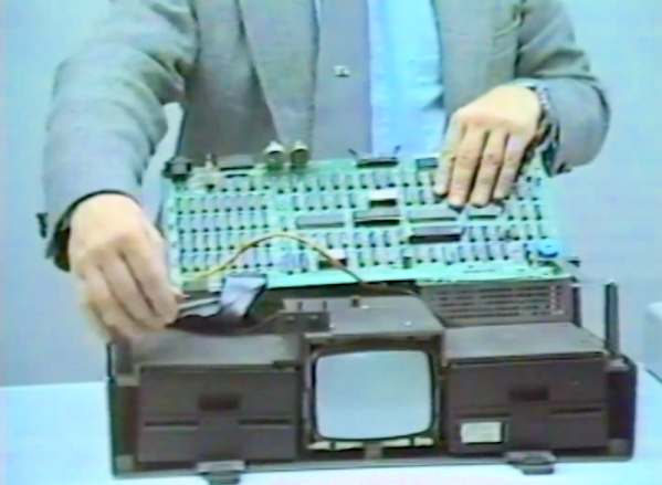
Fun fact, the Osborne 1 debuted with a price tag equivalent to about $5,000 in today’s value. With a gigantic 9″ screen and twin floppy drives (for making mix tapes, right?) the real miracle of the machine was its portability, something unheard of at the time. The retrocomputing trend is to lovingly and carefully restore these old machines to their former glory, regardless of how clunky or underpowered they are by modern standards. But sometimes they can’t be saved yet it’s still possible to gut and rebuild the machine with modern hardware, like with this Raspberry Pi used to revive an Osborne 1.

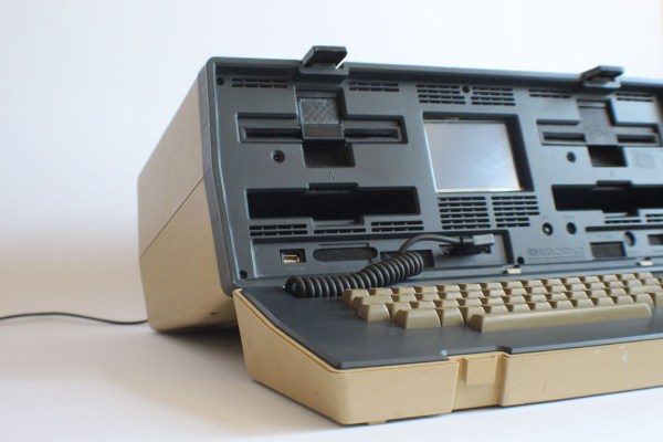
Purists will turn their nose up at this one, and we admit that this one feels a little like “restoring” radios from the 30s by chucking out the original chassis and throwing in a streaming player. But [koff1979] went to a lot of effort to keep the original Osborne look and feel in the final product. We imagine that with the original guts replaced by a Pi and a small LCD display taking the place of the 80 character by 24 line CRT, the machine is less strain on the shoulder when carrying it around. (We hear the original Osborne 1 was portable in the same way that an anvil is technically portable.) The Pi runs an emulator to get the original CP/M experience; it even runs Wordstar. The tricky part about this build was making the original keyboard talk to the Pi, which was accomplished with an Arduino that translates key presses to USB.

As an aside, if reading this has given you a twinge of nostalgia and you’re on the Eastern seaboard you may want to check out more vintage gear at the VCF East this weekend. If you hail from Europe, get your hack on with CP/M and a retrocomputing badge at Hackaday Belgrade one wee from now.

We’ve seen the Raspberry Pi pressed into retrocomputing duty before, of course. Here’s one used to emulate a Commodore 1541 disk drive, and another in the laptop Clive Sinclair never built.

Continue reading “Suitcase Computer Reborn With Raspberry Pi Inside”

Reverse Engineering The Z80’s 16-bit Increment/Decrement Circuit

z80

Increment and decrement. They sound like simple functions. But even the simplest functions can get quite complex in a microprocessor design. Ken Shirriff has written up a great blog post about his reverse engineering of the Z80’s 16-bit increment/decrement circuit. The Zilog Z80 was one of the most popular microprocessors of the 70’s and 80’s. It was used in many classic computers such as the Osborne 1. These machines would often use the Z80 to run the popular CP/M operating system.

The increment/decrement circuit is responsible for updating the program counter register during normal (non branch) operations. The increment/decrement circuit also handles the stack pointer register during stack operations, as well as several other functions. One might wonder why a separate adder would be used when the microprocessor has a big ALU available to it. The answer is twofold. First the ALU is already in use handling user math operations. Secondly the increment/decrement circuit has to be fast. A generic ALU just won’t be fast enough.

One classic adding circuit is a Ripple Carry Adder. Ripple Carry Adders get the job done, but they are slow. Note slow is measured in nanoseconds here – there are no clocks involved in the circuit. The whole thing becomes a classic combinational logic optimization problem. Each layer of logic adds a gate delay to the circuit. As the carry has to ripple through all 16 bits, there are 16 gate delays before the final result is available at the outputs. Delays like these are what limits the maximum clock speed for a given circuit.

The Z80 uses some tricks in its increment/decrement circuit. The first is Carry-lookahead. A carry-lookahead circuit will calculate the carry values directly from the inputs. This reduces the gate delays significantly, but it requires more real estate on the die. A second trick is the carry-skip circuit. Carry-skip calculates the result for groups of bits rather than each bit individually. Again, it will reduce gate delays, at the cost of real estate. The actual Z80 implementation uses a mix of both circuits. Several other “helper” circuits are also used. Surprisingly the Z80 has specific logic just to check for 1 (0x0001) on the internal address bus. This circuit is used during memory move loops to inform other parts of the chip that a loop is about to complete.