Followup: Troll Physics Solved

A month ago, we saw a marvelous demonstration of troll physics from YouTube user [Fredzislaw100]. In his video, we saw a circuit of three switches and three LEDs wired in series and but not acting like the should. A lot of the comments for this post elicited reasonable explanations like modifying the battery or pure camera wizardry via After Effects. Thankfully, [Alan] stepped in and showed us how it was done. The solution uses two AC power sources with diodes in two of the switches and LEDs and inductors in the third pair. [Alan]’s build was rather large compared to the original video, so we were wondering how this circuit could be made invisible.

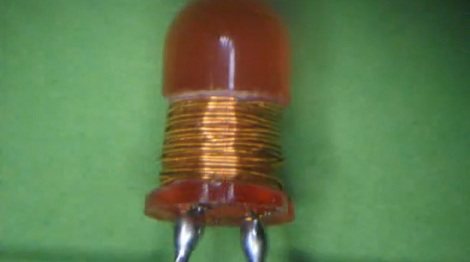
[Fredzislaw100] just posted a video on how he did it. Like [Alan]’s build, it uses two AC power sources, diodes, and inductors. In contrast to every single guess about where the circuit is hidden, the majority of the build is inside the battery connector. [Fredzislaw] did some amazing work hiding a 74LV132 quad NAND Schmitt trigger inside the battery connector. The diodes were easily hidden on LEDs 1 and 3 with some red nail polish, but we’re amazed by the inductor built into the LED seen in the title pic.

So there you go. With a ton of electronics know-how and an extremely steady hand (and a microscope), you too can build your own troll circuit. Check out the video after the break.

Continue reading “Followup: Troll Physics Solved”

Ask Hackaday: Troll Physics Edition

[Martin] sent in two videos he found while cruising the tubes. The first video is a simple circuit with a resistor, three switches, and three LEDs. All the components are soldered together right in front of the camera. When a battery is connected, turning the first switch on makes the first LED light up. Turning the second switch on makes the second LED light up, and the same thing goes for the third switch and LED. Obviously we’re dealing with powers that are incomprehensible with even several cups of coffee.

The second video features the same resistor/switches/LEDs, this time in a parallel circuit. Turning on the first switch makes the first LED light up, and the second switch makes the second LED light up. Truly we are dealing with an expert in troll physics.

This is probably something really benign and uninteresting, but it sure is enough to wake up enough brain cells on a Monday morning. We’re not going to hypothesize, so check out the comments where we expect the correct answer to be.

Continue reading “Ask Hackaday: Troll Physics Edition”

Driving And Old Receipt Printer

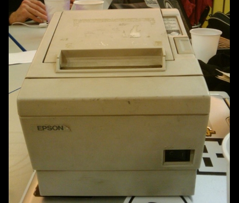
It seems like receipt printers are pretty popular as hacking targets lately. Aside from the wasted paper, they cooler than plain old blinking LEDs and we’d image there’s a ton of them floating around out there as advances in technology have prompted retailers to trade in the bulky dinosaurs for slimmer thermal printers. [Philip Hayton] picked up this Epson model at some type of equipment sale and set to work figuring out how to control it.

This unit is addressed via a parallel interface. After assessing the pinout and searching a bit for protocol information [Philip] hooked up his Arduino and printed out a fitting first message that reads: “Hello World”. He’s got a few tricks you can learn from when trying to talk to hardware with which you are not well acquainted.

Need a reason to go out and find your own receipt printer? Check out this paper-based gaming system for some inspiration. Now develop your own paper recycling setup and we can file this one under ‘green hacks‘.

[Thanks Andy]

Revive A DockStar And Get So Much More

[Firestorm_v1] has done a fabulous writeup on not only resurrecting his dead DockStar with JTAG, but also includes some handy techniques and useful information that could be used with other hardware and JTAG equipped devices.

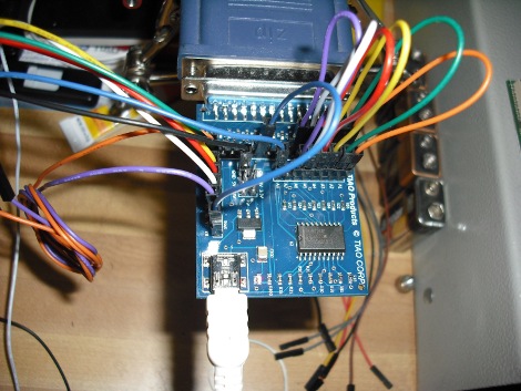
The tutorial itself goes into the details of finding the JTAG, correctly identifying the ports and making an adapter cable. Then wiring a TIAO Parallel JTAG kit and finally the flash and upload of firmware to the deceased Dockstar to give it new life.

While the fun stops a little short, we’ll be sure to keep an eye out for [Firestorm_v1’s] future plans involving these surprisingly useful (read: hackable) storage devices, “roving USB camera with WiFi” we hear?

WRT54GL, Meet Alice

When it comes to routers, there is one that is hacker’s favorite, the WRT54GL. But a slightly lesser known company, Pirelli with their “Alice Gate2 plus Wi-Fi”, seems to be a popular choice among our Italian friends.

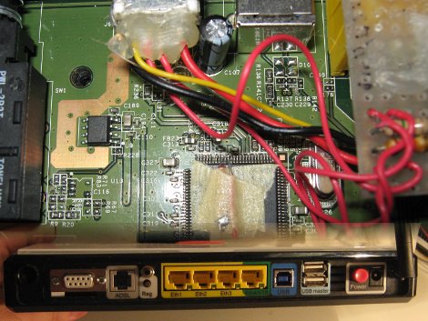
[Esteban] has done everything from installing serial and parallel ports, to unlocking firmware while installing Debian. Our personal favorite is the creative wiring of an additional USB port, where he had to custom create a power circuit to run his webcam and external drive.

[Thanks Marco]

[Update: It would appear Roleo, Beghiaro, and Zibri did the actual grunt work at ilpuntotecnicoeadsl and Esteban simply wrote the guides. Thanks for your hard work and hacking skills guys!]

Step-a-sketch

[Chris] is getting his feet wet with Computer Numerical Control starting with an Etch-a-Sketch interface. This is a great way to start out because the really tough parts of the project are already inside of the toy. He’s replaced the two white knobs with stepper motors and connected them through a mosfet network to a PIC 16f84a. The PIC then gets its commands from a computer via the parallel port.

A video of the CNC machine can be seen after the break. He needs to add a frame to increase the precision of the images drawn but this first attempt is pretty good. We prefer to have the computer in charge of the design because controlling an Etch-a-Sketch with a mouse doesn’t make our drawings any better. Continue reading “Step-a-sketch”

What’s The Worst Way To Transmit Video?

Perhaps the worst possible way to transmit video would be to send all pixel data in parallel.  That’s exactly how [Gebhard Sengmüller’s] parallel image device works. To be fair, this is an art piece called “A Parallel Image” that addresses the concept of where we would be if serial data transmission had never come to fruition. The brochure (PDF) accompanying the exhibit gives the juicy details we’re always looking for.

The device consists of a photo sensor unit and a display unit. Both are one-square-meter stripboard panels made of epoxy. The sensor unit consists of a 50×50 grid of photo-conductors that have their counterparts in the 50×50 grid of light bulbs on the display unit. Things start to get pretty crazy when you throw in the 7500 meters of magnet wire that connect the 2500 pixel sensor unit to the display unit.

You should be able to put together how this works. The sensors pick up light and then effect the brightness of the corresponding light bulbs. The result is an interesting image, and a nightmare of wire porn that would drive any TV repairman to drink.

Continue reading “What’s The Worst Way To Transmit Video?”