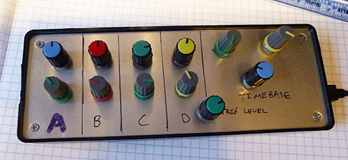
[Colin] loves his PicoScope, a USB based “headless” oscilloscope. While using it he found himself longing for a classic oscilloscope interface. Mouse clicks just weren’t a replacement for grabbing a dial and twisting it. To correct the situation he created his USB-Connected Box-o-Encoders. The box maps as a USB keyboard, so it will work with almost any program.
[Colin] started by finding encoders. There are plenty of choices – splined or flatted shaft, detents or no detents, panel, PCB, or chassis mount. He settled on an encoder from Bourns Inc. which uses an 18 spline shaft. His encoder also includes a push button switch for selection. With encoders down, knobs were next. [Colin] chose two distinct styles. The two knob styles aren’t just decorative. The user can tell which row of knobs they are on by touch alone. Electronics were made simple with the use of a Teensy++ 2.0. [Colin] used a ATUSBKey device running Teensy software, but says the Teensy would have been a much better choice in terms of size and simplicity.
Once everything was wired into the box, [Colin] found his encoders would “spin” when the knobs were turned. They are actually designed to be PCB mounted, and then screwed into a control panel. Attempts to tighten down the panel mounting nut resulted in a broken encoder. Rather than redesign with purely panel mounted encoders, [Colin] used a dab of epoxy to hold the encoder body in place.


