Wago Terminals Make This Ham Radio Dipole Light And Packable

For the amateur radio operator with that on-the-go lifestyle, nothing is more important than having your gear as light and packable as possible. If you’re lugging even a modest setup out into the woods, every ounce counts, which is why we love projects like this packable dipole antenna feedpoint.

At its simplest, a dipole antenna is just two pieces of wire cut to a specific, frequency-dependent length connected to a feedline. In practical terms, though, complications arise, such as keeping common-mode currents off the feedline and providing sturdy mechanical support for the antenna to suspend it safely. [Ham Radio Dude]’s design handles both those requirements while staying as small and packable as possible. The design starts with a bifilar 1:1 current balun, which is wound on an FT82-43 ferrite toroid with 22 AWG magnet wire. One side of the balun is connected to a BNC connector while the other is connected to a pair of Wago splice connectors that are glued together. A loop of paracord for mechanical strain relief is added, and the whole thing gets covered in heat-shrink tubing. The antenna is deployed by attaching a feedline to the BNC, clipping quarter-wave wires into the Wago terminals, and hoisting the whole thing aloft. Full build details are in the video below.

People will no doubt be quick to point out that these Wago terminals are rated for a minimum of 18 AWG wire, making them inappropriate for use with fine magnet wire. True enough, but [Dude] was able to get continuity through the Wagos, so the minimum gauge is probably more of an electrical code thing. Still, you’ll want to be careful that the connections stay solid, and it might pay to look at alternatives to the Wago brand, too. Continue reading “Wago Terminals Make This Ham Radio Dipole Light And Packable”

You’ve Got The Portable Radio, Now What About The Antenna?

There’s an old saying in the amateur radio community that when it comes to antennas all you need is a piece of wet string. This may be a little fanciful, but it’s certainly true that an effective antenna can be made with surprisingly little in the way of conductor. It’s something [Evan Pratten VZ3ZZA] demonstrates amply with a description of the antenna he took camping in a Canadian provincial park.

Most of us would try some form of dipole on our adventures, but the antenna he’s using caught our eye as it’s described as an end-fed half-wave, but it has both a half-wave and quarter-wave element. Made from speaker cable or in this case thin mains cable for lamps, it’s obviously far from a perfect match and requires an ATU, but it generates an impressive array of FT4 contacts on a pretty meagre power level. We particularly like his in-plain-sight test run in the parking lot of a supermarket.

We frequently talk about the diversity of pursuits in amateur radio aside from that of the chequebook ham, and this project shows one of those. The world of QRP, operating at extreme low power, is not expensive to enter and can be extremely rewarding.

Tiny Transceiver Gets It Done With One Transistor

When we first spotted the article about a one-transistor amateur radio transceiver, we were sure it was a misprint. We’ve seen a lot of simple low-power receivers using a single transistor, and a fair number of one-transistor transmitters. But both in one package with only a single active component? Curiosity piqued.

It turns out that [Ciprian Popica (YO6DXE)]’s design is exactly what it says on the label, and it’s pretty cool to boot. The design is an improvement on a one-transistor transceiver called “El Pititico” and is very petite indeed. The BOM has only about fifteen parts including a 2N2222 used as a crystal-controlled oscillator for both the transmitter and the direct-conversion receiver, along with a handful of passives and a coupe of hand-wound toroidal inductors. There’s no on-board audio section, so you’ll have to provide an external amplifier to hear the signals; some might say this is cheating a bit from the “one transistor” thing, but we’ll allow it. Oh, and there’s a catch — you have to learn Morse code, since this is a CW-only transmitter.

As for construction, [Ciprian] provides a nice PCB  layout, but the video below seems to show a more traditional “ugly style” build, which we always appreciate. The board lives in a wooden box small enough to get lost in a pocket. The transceiver draws about 1.5 mA while receiving and puts out a fairly powerful 500 mW signal, which is fairly high in the QRP world. [Ciprian] reports having milked a full watt out of it with some modifications, but that kind of pushes the transistor into Magic Smoke territory. The signal is a bit chirpy, too, but not too bad.

We love minimalist builds like these; they always have us sizing up our junk bin and wishing we were better stocked on crystals and toroids. It might be good to actually buckle down and learn Morse too.

Continue reading “Tiny Transceiver Gets It Done With One Transistor”

A Tiny Tuner For The Low Power Ham

Something that all radio amateurs encounter sooner or later is the subject of impedance matching. If you’d like to make sure all that power is transferred from your transmitter into the antenna and not reflected back into your power amplifier, there’s a need for the impedance of the one to match that of the other. Most antennas aren’t quite the desired 50 ohms impedance, so part of the standard equipment becomes an antenna tuner — an impedance matching network. For high-power hams these are big boxes full of chunky variable capacitors and big air cored inductors, but that doesn’t exclude the low-power ham from the impedance matching party. [Barbaros Aşuroğlu WB2CBA] has designed the perfect device for them: the credit card ATU.

The circuit of an antenna tuner is simple enough, two capacitors and an inductor in a so-called Pi-network because of its superficial resemblance to the Greek letter Pi. The idea is to vary the capacitances and inductance to find the best match, and on this tiny model it’s done through a set of miniature rotary switches. There are a set of slide switches to vary the configuration or switch in a load, and there’s even a simple matching indicator circuit.

We like this project, in that it elegantly provides an extremely useful piece of equipment, all integrated into a tiny footprint. It’s certainly not the first ATU we’ve brought you.

Thanks [ftg] for the tip!

Emails Over Radio

The modern cellular network is a marvel of technological advancement that we often take for granted now. With 5G service it’s easy to do plenty of things on-the-go that would have been difficult or impossible even with a broadband connection to a home computer two decades ago. But it’s still reliant on being close to cell towers, which isn’t true for all locations. If you’re traveling off-grid and want to communicate with others, this guide to using Winlink can help you send emails using a ham radio.

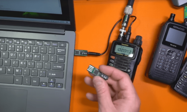
While there are a number of ways to access the Winlink email service, this guide looks at a compact, low-power setup using a simple VHF/UHF handheld FM radio with a small sound card called a Digirig. The Digirig acts as a modem for the radio, allowing it to listen to digital signals and pass them to the computer to decode. It can also activate the transmitter on the radio and send the data from the computer out over the airwaves. When an email is posted to the Winlink outbox, the software will automatically send it out to any stations in the area set up as a gateway to the email service.

Like the cellular network, the does rely on having an infrastructure of receiving stations that can send the emails out to the Winlink service on the Internet; since VHF and UHF are much more limited in range than HF this specific setup could be a bit limiting unless there are other ham radio operators within a few miles. This guide also uses VARA, a proprietary protocol, whereas the HF bands have an open source protocol called ARDOP that can be used instead. This isn’t the only thing these Digirig modules can be used for in VHF/UHF, though. They can also be used for other digital modes like JS8Call, FT8, and APRS.

Continue reading “Emails Over Radio”

Altoids Tin Spy Radio Goes Solid State

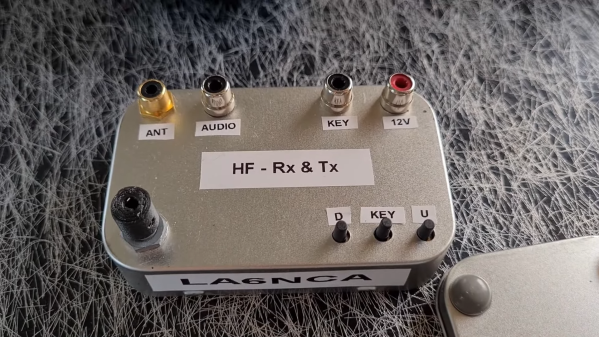
[Helge Fykse (LA6NCA)] has a type, as they say. At least as far as radios are concerned, he seems to prefer elegant designs that keep the BOM to the minimum needed to get the job done. And Altoids tins — he really seems to like putting radios in Altoids tins.

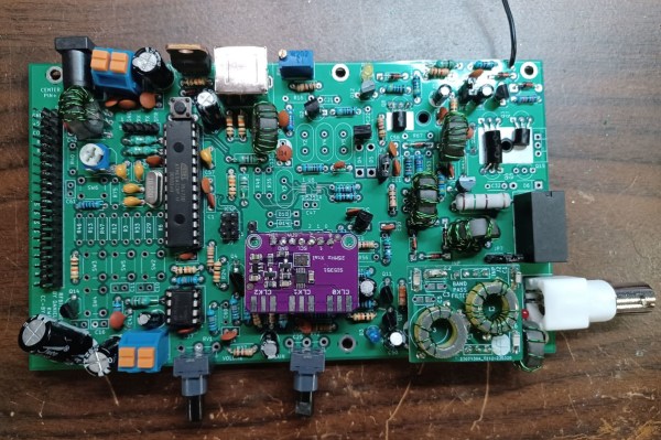
This QRP transceiver for the 60-meter amateur radio band is a perfect example of that ethos. For the unfamiliar, QRP is Morse code shorthand for decreased power, and is generally used when hams are purposely building and operating radios that radiate very little power, typically below a watt. For this transceiver, [Helge] chose to use modern components, a marked but interesting departure from his recent tube-powered spy radios. The design is centered on a custom oscillator board he designed using an Arduino Pro Mini and an Si5351 oscillator chip. Other components include an ADE-1ASK frequency mixer, an antenna tuner module that can be swapped out for operating on different bands, a receiver that’s little more than a couple of op-amps, and a Darlington pair for an RF power amplifier. Everything fits neatly on a piece of copper-clad board inside the tin box.

As is his tradition, [Helge] was on the air in the field with this radio almost before the solder had time to cool. His first contact was a 240-km shot to a friend, who reported a fine signal from this little gem. And that’s with just powering it off a 9-volt battery when it’s designed to the typical 12-volt supplies hams favor; he estimates this resulted in a signal of about 200 mW. Not too shabby.

Honestly, we’d love to learn more about that oscillator board [Helge] used, and maybe get a schematic for it. We found a little bit about it on his web page, but not the juicy details. If you’re out there, [Helge], please share the wealth.

Continue reading “Altoids Tin Spy Radio Goes Solid State”

Off-Grid Radio Also Repairable Off-Grid

Low-power radios, often referred to in the amateur radio community as QRP radios, have experienced a resurgence in popularity lately. Blame it on certain parts of the hobby become more popular, like Parks on the Air (POTA) or Summits on the Air (SOTA). These are events where a radio operator operates off-grid at remote parks or mountaintops. These QRP rigs are a practical and portable way to make contacts. You would think that a five- or ten-watt rig running on batteries would be simple. Surprisingly, they can be enormously complex and expensive. That’s why [Dr. Daniel Marks] built the RFBitBanger, a QRP radio designed to not only be usable off-grid but to be built and maintained off-grid as well.

The radio accomplishes this goal by being built out of as many standard off-the-shelf components as possible. It eschews modern surface-mount components in favor of the much more accessible through-hole parts, including the ATMEGA328P at the center of the build. A PCB design is also available, but it can be built on perf board nearly as easily. The radio supports any mode a QRP operator might use, including CW, SSB, RTTY, and a new mode designed explicitly for this radio called SCAMP which is a low bandwidth, low SNR digital mode built into the Arduino-based firmware. It’s a single-band radio, but any band between 20 and 80 meters can be selected with pluggable filters.

As far as bomb-proof radios go, we can’t imagine a better way to live out an apocalypse than with a radio like this. As long as there’s a well-stocked parts drawer around, this radio could theoretically reach around the world without worrying about warranty claims, expensive parts, or even a company going out of business or not stocking parts for old radios anymore. There’s also more information about this build at the Open Research Institute for those interested. And, if you’re wondering how useful any radio could be using only five watts of transmitter power, take a look at this in-depth look at QRP radio operation.

Thanks to [Stephen Walters] for the tip.