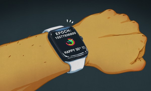
Good morning everyone, and what a lovely start to the new year it is, because it’s your birthday! Happy birthday, it’s your 50th! What’s that you say, you aren’t 50 today? (Looks…) That’s what all these internet databases say, because you’ve spent the last decade or so putting 1970-01-01 as your birth date into every online form that doesn’t really need to know it!
It’s been a staple for a subset of our community for years, to put the UNIX epoch, January 1st 1970, into web forms as a birth date. There are even rumours that some sites now won’t accept that date as a birthday, such is the volume of false entries they have with that date. It’s worth taking a minute though to consider UNIX time, some of its history and how its storage has changed over the years.
Reading the temperature of your environment is pretty easy right? A quick search suggests the utterly ubiquitous DHT11, which speaks a well documented protocol and has libraries for every conceivable microcontroller and platform. Plug that into your Arduino and boom, temperature (and humidity!) readings. But the simple solution doesn’t hit every need, sometimes things need to get more esoteric.
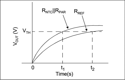
The technique summarized by an image from Microchip Appnote AN685
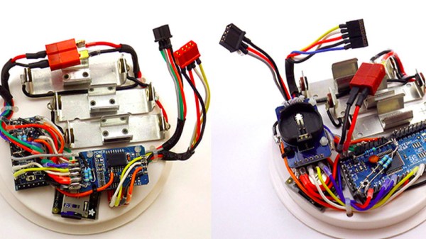
For years we’ve been watching [Edward]’s heroic efforts to build accessible underwater sensing hardware. When we last heard from him he was working on improving the accuracy of his Arduino’s measurements of the humble NTC thermistor. Now the goal is the same but he has an even more surprising plan, throw the ADC out entirely and sample an analog thermistor using digital IO. It’s actually a pretty simple trick based on an intuitive observation, that microcontrollers are better at measuring time than voltage.
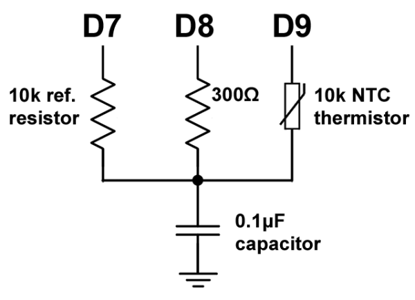
The basic circuit
The circuit has a minimum of four components: a reference resistor, the thermistor, and a small capacitor with discharge resistor. To sense you configure a timer to count, and an edge interrupt to capture the value in the timer when its input toggles. One sensing cycle consists of discharging the cap through the discharge resistor, enabling the timer and interrupt, then charging it through the value to measure. The value captured from the timer will be correlated to how long it took the cap to charge above the logic-high threshold when the interrupt triggers. By comparing the time to charge through the reference against the time to charge through the thermistor you can calculate their relative resistance. And by performing a few calibration cycles at different temperatures ([Edward] suggests at least 10 degrees apart) you can anchor the measurement system to real temperature.
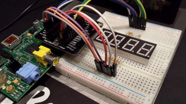
The whims of the tides can make walking near the ocean a less than pleasant experience. A beautiful seascape one day may appear as a dismal, mucky, tidal flat the next. Frustrated over these weary walks, [Average Man] created a tidy tide tracker to predict propitious promenade periods.
A Raspberry Pi A+ pulls tide timing information off the web by scraping a web page using Python code. The time for the high tide, when the estuary will be full of water, is shown on a 4-digit 7-seg display. It’s all sandwiched between two smoked black panels to provide a neat case while still letting the LEDs show through.
It’s great to learn programming from others, but it’s even better if you learn them well enough to remember, re-use and combine that code later on as well.
The display chips are mounted on a product of his own, the no longer available ProtoPal board. This is a Pi A+ size board with 288 prototyping holes and the standard connector for mounting on the Pi GPIO header. It keeps the project neat and clean.
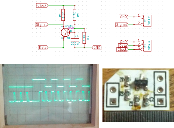
The WS28xx offerings place a microcontroller inside an RGB LED, allowing them to be individually addressed in very long chains or large matrices (still a chain but different layout). But the timing scheme used to address them doesn’t play well with traditionally available microcontroller peripherals. [Brett] had been intrigued by some of the attempts to bend hardware SPI to the will of the WS2811 — notably [Cunning_Fellow’s] work featured in this post. He took it a great step forward by simplifying the driver to just one transistor, three resistors, and a capacitor.
Click through the link above for his step-by-step description of how the circuit works (it’s not worth re-explaining here as he does a very concise job himself). The oscilloscope above shows the SPI signal on top and the resulting timing signal below. You will notice the edges aren’t very clean, which requires the first pixel to be very close to the driver or risk further degradation. But, since the WS28xx drivers feature a repeater which cleans up signals like this, it’s smooth sailing after the first pixel.
We like [Tim’s] drive for improvement. He wrote a WS2812 driver library that works with AVR and ARM Cortex-M0 microcontrollers, but he wasn’t satisfied with how much of the controller’s resources the library used to simply output the required timing signal for these LED modules. When he set out to build version 2.0, he dug much deeper than just optimizing his own code.
We remember [Tim] from his project reverse engineering a candle flicker LED. This time, he’s done more reverse engineering by comparing the actual timing performance of the WS2812(B) module with its published specs. He learned that although several timing aspects require precision, others can be fudged a little bit. To figure out which ones, [Tim] used an ATtiny85 as a signal-generator and monitored performance results with a Saleae logic analyzer. Of course, to even talk about these advances you need to know something about the timing scheme, so [Tim] provides a quick run-through of the protocol as part of his write-up.