A Simpler Method To Make Optical Fiber With 3D Printing

There are a lot of remarkable uses for optical fiber, chief among them being telecommunications and imaging. While fiber can be produced for a better price than copper wire equivalents, they’re still not easy or cheap to manufacture.

Silica fibers require spinning tubes on a lathe, which requires the fiber’s core to be precisely centered. A new method by researchers based at the University of Technology, Sydney offers a simpler method using additive manufacturing.

There are still challenges in producing silica fiber, however – unlike commonly drawn polymer materials, silica requires high temperatures, up to 1900 degrees Celsius, to 3D print. Past attempts at glass printing using fused deposition modeling with high-temperature nozzles to pump out molten silica have been slowed by the viscosity of molten glass.

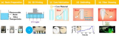
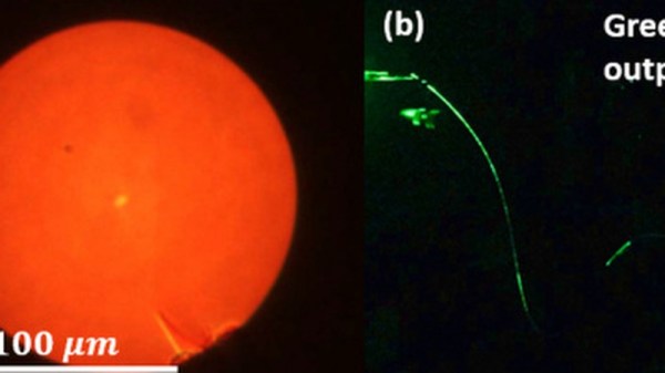
In order to overcome the temperature problem, composite materials consisting of a polymer with a lower melting point and silica nanoparticles are used instead. In addition, the researchers opted to use a direct laser writing printer. The technique involves drawing the molten material and pulling out the optical fiber. After the polymer and impurities are debinded and removed, it’s only an issue of sintering the silica to fuse the forms back together.

The method has been used to fabricate a preform that can be used for multi- or single-node fibers. While the technique isn’t perfected quite yet, it holds promise for reduced fabrication and material costs, as well as eliminating labor risks from the lathe-based work.

[Thanks to Qes for the tip!]

FiberGrid: An Inexpensive Optical Sensor Framework

When building robots, or indeed other complex mechanical systems, it’s often the case that more and more limit switches, light gates and sensors are amassed as the project evolves. Each addition brings more IO pin usage, cost, potentially new interfacing requirements and accompanying microcontrollers or ADCs. If you don’t have much electronics experience, that’s not ideal. With this in mind, for a Hackaday prize entry [rand3289] is working on FiberGrid, a clever shortcut for interfacing multiple sensors without complex hardware. It doesn’t completely solve the problems above, but it aims to be a cheap, foolproof way to easily add sensors with minimal hardware needed.

The idea is simple: make your sensors from light gates using fiber optics, feed the ends of the plastic fibers into a grid, then film the grid with a camera. After calibrating the software, built with OpenCV, you can “sample” the sensors through a neat abstraction layer. This approach is easier and cheaper than you might think and makes it very easy to add new sensors.

Naturally, it’s not fantastic for sample rates, unless you want to splash out on a fancy high-framerate camera, and even then you likely have to rely on an OS being able to process the frames in time. It’s also not very compact, but fortunately you can connect quite a few sensors to one camera – up to 216 in [rand3289]’s prototype.

There are many novel uses for this kind of setup, for example, rotation sensors made with polarising filters. We’ve even written about optical flex sensors before.

Building An LED Source For A Fiber Optic Ring Light

[Peter] has finished up his fiber optic microscope light source. When we last visited [Peter] he created a dimmer circuit for a 10 watt LED. That LED driver has now found its final home in [Peter’s] “Franken-ebay scope”, a stereo microscope built from parts he acquired over several years. Stereo microscopes scopes like these are invaluable for working on surface mount parts, or inspecting PCB problems. [Peter] had the fiber optic ring and whip, but no light source. The original source would have been a 150W Halogen lamp. The 10 watt led and driver circuit was a great replacement, but he needed way to interface the LED to the fiber whip. Keeping the entire system cool would be a good idea too.

This was no problem for [Peter], as he has access to a milling machine. He used an old CPU heat sink from his junk box as the base of the light source. The heat sink was drilled and tapped for the LED. The next problem was the actual fiber whip interface. For this, [Peter] milled a custom block from aluminum bar stock. The finished assembly holds the LED, driver, and the fiber whip. A sheet metal bracket allows the entire assembly to be mounted on the microscope’s post.  We have to admit, if we were in [Peter’s] place, we would have gone with a cheap LED ring light. However, the end result is a very clean setup that throws a ton of light onto whatever [Peter] needs magnified.

Continue reading “Building An LED Source For A Fiber Optic Ring Light”