LED Matrix Hack Chat

Join us on Wednesday, June 9 at noon Pacific for the LED Matrix Hack Chat with Garrett Mace!

It’s pretty amazing how quickly light-emitting diodes went from physics lab curiosity to a mainstream commodity product made in the millions, if not billions. Everything about LEDs has gotten better, smaller, and cheaper over the years, going from an “any color you want as long as it’s red” phase to all the colors of the rainbow and beyond in a relatively short time. LEDs have worked their way into applications that just didn’t seem likely not that long ago, like architectural lighting, automotive applications, and even immense displays covering billboards, buildings, and sporting venues with multicolor, high-resolution displays.

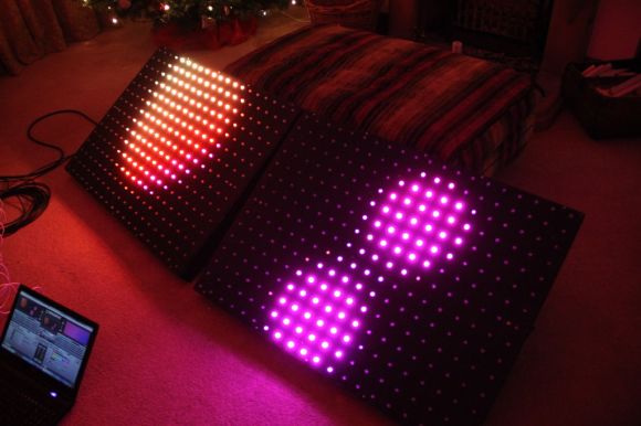
It’s that latter application that seems to have provided a boon to electronics hobbyists, in the form of cheap and plentiful LED matrix modules. These are easily sourced at the usual places, and with their tightly packed pinpoints that can show any color at any intensity, they have a ton of fun and useful applications for the hacker. But how exactly do you put them to use? Usually the electronics end is pretty straightforward, but some of the math involved in figuring out how to address all these LEDs can be a little mind-bending.

To help us sort all this out, Garrett Mace will drop by the Hack Chat. You’ve probably seen Garrett’s cool LED matrix shades, which have gone through a ton of revisions and are a much-copied fashion accessory among the cool hackers. They look simple, but there are tricks to making them work right, and Garrett will share his secrets. Come with your questions on putting LED matrix modules to work, especially those odd-size modules and strange arrangements that defy simple Cartesian coordinates.

join-hack-chatOur Hack Chats are live community events in the Hackaday.io Hack Chat group messaging. This week we’ll be sitting down on Wednesday, June 9 at 12:00 PM Pacific time. If time zones have you tied up, we have a handy time zone converter.

Click that speech bubble to the right, and you’ll be taken directly to the Hack Chat group on Hackaday.io. You don’t have to wait until Wednesday; join whenever you want and you can see what the community is talking about.

An Even Larger Array Of Many LEDs And No Ping-Pong balls

Color Led Matrix

[George] has gone pro with his latest RGB LED panel. We’ve chronicled [George’s] journey toward the elusive land of LED nirvana for a couple of years now. He started with an 8×8 rainbow board of many ping-pong balls. When that wasn’t enough, he upped the ante to a 32×16 array of ping-pong balls. Still not satisfied, [George] has now increased the size to two 20×15 panels, for a total of 600 LEDs. While this is only a modest size increase from the previous incarnation, the major changes here have been in the design and construction of the array.

[George] found himself using his LED panels in some professional settings. The stresses of moving and rigging the panels revealed several design weaknesses. The point to point discrete LED design tended to short, leading to troubleshooting by poking at wires in a dark club. The control code was also a mixed bag of solderlab’s code, [George’s] code, and various scripts. Even the trademark ping-pong ball light diffusers were a problem, as they created a fire hazard. [George] took all the lessons from the first and second LED arrays and started a new design – the MX3. The panel frames were constructed by a professional metal shop. Starting with a square steel tube backbone, and aluminum panel shell was welded into place. The steel tube provides a hardpoint mount for any number of rigging options. The front panels are medium-density fibreboard, treated with a fire-retardant paint.

The electronics have also changed. Gone are the individual RGB LEDs. [George] has switched over to the common WS2812 LED strings. Panel mounted Raspberry Pis control the LED strings. Communication is via Art-Net, an Ethernet implementation of the common DMX512 protocol commonly used in stage lighting. The final result looks great.  We’re impressed with how much [George] has accomplished at such a young age (He was 16 last June).

Continue reading “An Even Larger Array Of Many LEDs And No Ping-Pong balls”

Status Light Tells You The Code Is Borked Again

status light

[Arthur] is teaching himself product development. Rather than create a few mock-up products, he’s taking the path of designing real devices he can use. His current device is a status light for automated software tests.  We’ve seen test and GitHub status lights before, however this is the first one to integrate with an outside web service. The status light’s state is based upon output from CodeShip, an online continuous deployment test engine.

The electronic design is simple. An Electric Imp retrieves test status data from CodeShip. The Imp then sends the status data over two GPIO lines to an AdaFruit Trinket. The Trinket controls a NeoPixel ring. A green ring indicates all tests are passing. Purple means tests are in progress. A spinning red ring (of death) means one or more tests have failed. Power is supplied via a mini USB connector.

[Arthur] spent quite a bit of time on the mechanical design of the status light as well. All the parts are 3D printed. This allowed him to quickly go through several revisions of each part. We like the use of white PLA for a frosted effect on the top section of the light, as it diffuses the eye piercing glow from all those RGB LEDs. As a finishing touch, [Arthur] created a fake product page for his light. He doesn’t have any plans to sell it, but we hope he drops the source and STL files so we can create one of our own.

Continue reading “Status Light Tells You The Code Is Borked Again”

Get Tangled Up In EL Wire With Freaklabs

[Akiba] over at Freaklabs has been working with electroluminescent (EL) wire.  An entire dance company worth! We know [Akiba] from his post tsunami radiation monitoring work with the Tokyo Hackerspace. Today he’s one of the engineers for Wrecking Crew Orchestra, the dance company that put on the viral “Tron Dance” last year. Wrecking Crew Orchestra just recently put on a new production called Cosmic Beat. Cosmic Beat takes Wrecking Crew’s performances to a whole new level by adding stage projection mapping and powerful lasers, along with Iron Man repulsor style hand mounted LEDs.

As one might expect, the EL wire costumes are controlled by a computer, which keeps all the performers lighting effects in perfect time. That’s where [Akiba] came in. The modern theater is awash in a sea of RF noise. Kilowatts of lighting are controlled by triacs which throw out tremendous amounts of noise. Strobes and camera flashes, along with an entire audience carrying cell phones and WiFi devices only add to this. RF noise or not, the show must go on, and The EL costumes and LEDs have to work. To that end, [Akiba] He also created new transmitters for the group. He also changed  the lighting booth mounted transmitter antenna from an omnidirectional whip to a directional Yagi.

The EL wire itself turned out to be a bit of a problem. The wire wasn’t quite bright enough. Doubling up on the wire would be difficult, as the dancers are already wearing 25 meters of wire in addition to the control electronics. Sometimes best engineering practices have to give way to art, so [Akiba] had to overdrive the strings. This means that wires burn out often. The dance troupe has gotten very good at changing out strands of wire during and between shows. If you want a closer look, there are plenty of pictures available on [Akiba’s] flickr stream.

Continue reading “Get Tangled Up In EL Wire With Freaklabs”

Building An LED Source For A Fiber Optic Ring Light

[Peter] has finished up his fiber optic microscope light source. When we last visited [Peter] he created a dimmer circuit for a 10 watt LED. That LED driver has now found its final home in [Peter’s] “Franken-ebay scope”, a stereo microscope built from parts he acquired over several years. Stereo microscopes scopes like these are invaluable for working on surface mount parts, or inspecting PCB problems. [Peter] had the fiber optic ring and whip, but no light source. The original source would have been a 150W Halogen lamp. The 10 watt led and driver circuit was a great replacement, but he needed way to interface the LED to the fiber whip. Keeping the entire system cool would be a good idea too.

This was no problem for [Peter], as he has access to a milling machine. He used an old CPU heat sink from his junk box as the base of the light source. The heat sink was drilled and tapped for the LED. The next problem was the actual fiber whip interface. For this, [Peter] milled a custom block from aluminum bar stock. The finished assembly holds the LED, driver, and the fiber whip. A sheet metal bracket allows the entire assembly to be mounted on the microscope’s post.  We have to admit, if we were in [Peter’s] place, we would have gone with a cheap LED ring light. However, the end result is a very clean setup that throws a ton of light onto whatever [Peter] needs magnified.

Continue reading “Building An LED Source For A Fiber Optic Ring Light”

Simple 10 Watt LED Driver Is Hot Stuff

[Peter] needed to drive a high power LED for his microscope. Rather than pick up a commercial LED driver, he built a simple constant current LED driver and fan control. We’ve featured [Peter’s] pumpkin candle LED work here on Hackaday in the past. Today he’s moving on to higher power LEDs. A 10 watt LED would be a good replacement light source for an old halogen/fiber optic ring light setup. [Peter] started with his old standby – an 8 pin Microchip PIC. In this case, a PIC12F1501. A PIC alone won’t handle a 10 watt LED, so he utilized a CAT4101 constant current LED driver from ON Semi. The PIC performs three tasks in this circuit. It handles user input from two buttons, generates a PWM signal to the LED driver, and generates a PWM signal for a cooling fan.

Control is simple: Press both buttons and the LED comes on full bright. Press the “up” button, and the LED can be stepped up from 10% to 100% in 10 steps.  The “down” button drops the LED power back down. [Peter] even had a spare pin. He’s currently using it as an LED on/off confirmation, though we’d probably use it with a 1wire temperature sensor as a backup to thermal protection built into the CAT4101. It may be overkill, but we’d also move the buttons away from that 7805 linear regulator. Being that this circuit will be used with a microscope, it may eventually be operated by touch alone. It would be a bit surprising to try to press a button and end up with a burnt fingertip!

Continue reading “Simple 10 Watt LED Driver Is Hot Stuff”

A POV Spinner Display With Arduino

pov-display

[Martin2250] has been working on a spinning disc style POV display. He’s posted his progress up on reddit. This hack is a great example of using what you have at your disposal. [Martin2250] is using an IR LED and photodiode to determine the rotational speed of the disc. He tried using the Arduino micros() function to delay between the photodiode pulse and turning on his LEDs. As [Martin2250] found out, micros() isn’t quite accurate enough for this purpose.  He’s since switched over to using the AVR’s native timers, and is getting much better results.

The disc in this build is actually a CD. [Martin2250] sanded away the label, then masked out his digits. He “painted” the CD with a black marker. Peeling off the tape revealed his stylized digits. Cardboard, hot glue, and visible LEDs were used to create four light boxes for the digits. The disc can display any four digits at once – perfect for a POV clock. We love the use of on-hand materials in this hack – bits of hard and balsa wood, liberal use of hot glue, and of course cardboard. The only thing missing in our eyes is some duct tape!