Air Wick Odor Detect Teardown

air_wick_odor_detect_teardown

[Hunter’s] wife came home from her latest extreme couponing session with a handful of free Air Wick Odor Detect air fresheners, and since they had so many of the things sitting around, he was compelled to take one apart to see what makes them tick.

The casing was secured with melted snap tabs which had to be cut, making disassembly a one-way street. Once opened, he found a trio of white label AA cells and an ARNIE COMPACT3 ISS.4 controller board, complete with an epoxy-sealed microcontroller. A similarly branded sensor board was attached to the controller, and he spotted a solenoid with a built-in nozzle for spraying air freshener as well.

The sensor board piqued his curiosity the most, and after some research he’s pretty sure that the Air Wick uses an Applied Sensor VOC air quality module to get the job done. The tiny sensor uses a special substrate containing electrodes, which measure the resistance of the sensing layer while it is heated to upwards of 400° C.  A change in resistance lets the air freshener know that it’s time to handle the odoriferous emanations floating about.

Thanks to [Hunter] for taking the time to tear the Air Wick down and letting us know what’s inside!

A Solar-Powered Automatic Chicken Coop

Although we’ve featured many chicken-related hacks here, this chicken coop features a solar-powered door to save one from having to open up the coop in the morning.  As [chrisatronics] puts it “keeping chickens has one major drawback: You have to get up with them in the early morning and open the door at the coop. Everyday. Including Sundays and holidays.” This would help explain why so many people seem to be hacking their coops.

Solar power may be an interesting idea in itself, but when coupled with the fact that a chicken coop isn’t necessarily near a power supply, this becomes a very expedient solution. Controlling the setup is a MSP430 microcontroller (programming featured here for Linux) with a salvaged windshield wiper gearmotor. [Chrisatronics] did a great job writing this hack up, so if you want to try this yourself, make sure to check out the article.

Also, don’t forget to check out the video after the break for the ‘coop in action! Continue reading “A Solar-Powered Automatic Chicken Coop”

ATtiny Hacks: ATtiny-controlled 4x4x4 LED Cube Has A Unique Design

ATtiny Hacks Theme Banner

simple_attiny_led_cube_charlieplexing

[Tom] recently started experimenting with Charlieplexing, and wrote in to share the 4x4x4 cube he built with an ATtiny24. Similar to this minimalist 4x4x4 LED cube we featured the other day, [Tom’s] version attempts to use the least pins possible to drive the LEDs, but in a different manner.

[Tom] didn’t want to sacrifice brightness, so he decided that the LEDs would have a 1/8 duty cycle. The problem is that the ATtiny’s I/O ports can’t support that kind of current so he needed a different means of driving the LEDs. Rather than employ any sort of shift register to control the LEDs, he opted to exclusively use transistors as he had done in previous projects.

For his Charlieplexed cube to use a total of 9 I/O pins he had to get creative with his design. He broke each level of the structure into two non-connected groups of LEDs, utilizing diagonal interconnects to get everything wired up properly.

It seems to work quite nicely as you can see in the video below. While it uses two more I/O lines than the other ATtiny cube we featured recently, we love the simple, shift register-less design.

Continue reading “ATtiny Hacks: ATtiny-controlled 4x4x4 LED Cube Has A Unique Design”

Roland 808 Synced To MIDI

Reading this week’s ATtiny-themed builds, [Thomas] was reminded one of his coolest builds. His midi808 project used an ATtiny2313 to sync a vintage Roland 808 drum machine to his Logic workstation.

Even though MIDI had been around for a few years when 808s were being made, the CPU in the 808 isn’t exactly up to the task of handling MIDI. Instead, the 808 used an interface known as DIN Sync that was designed to keep 808s, 707s, and 303s in time with each other. MIDI to DIN Sync boxes do did exist, but even the auxiliary equipment to use an 808 is getting hard to find.

The build takes a MIDI signal and passes it through an opto-isolator per the MIDI spec. The microcontroller reads the MIDI signal and passes it out through the DIN Sync port. The DIN Sync protocol is only 24 pulses per quarter note output with TTL voltages, and the project code is easy enough to follow. It’s a nice build for one of the greatest drum machines ever made. Listen to a track [Thomas] made with his new setup after the break.

Continue reading “Roland 808 Synced To MIDI”

3D-printable Laser Cutter

[peter] send in a reprappable laser cutter that he’s been working on. Even though he’s still having some problems with the accuracy of the beam over the entire square meter bed, it’s still an amazing build.

The build started off with a bunch of t-slot aluminum extrusions. After taking delivery of an absurdly large package containing a CO2 laser tube, [peter] started working on attaching motors to the axes. The optics travel the solid rods on pillow block bearings driven by the age-old stepper motor & timing belt drive.

The 1-square-meter of cut area on this machine is enormous for a homebrew laser cutter. [peter] discovered that once the necessary components are in place, it’s really how much aluminum you’d like to buy that becomes the limiting factor for the cut area. [peter] put the files for the 3D-printed carriages, brackets and mounts up on Thingiverse in the hopes his design can be improved by others.

[Dino] Builds A Simple Non-contact Voltage Detector

homemade_voltage_detector

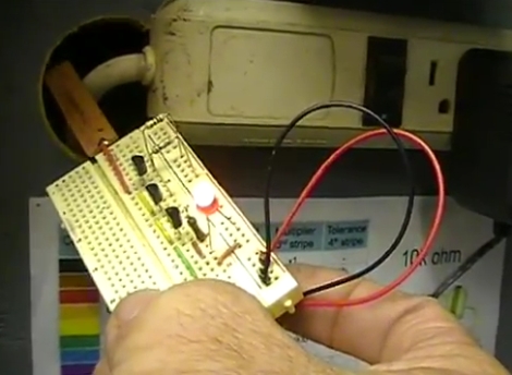
[Dino] is back with another installment of his Hack a Week series, and in this episode he is taking on what he promises will be the last transistor-based project – at least for a little while.

In the video embedded below, he shows off a homemade voltage detector circuit that he constructed using a trio of BC547 NPN transistors. The circuit is pretty simple though very useful all the same. At one end, the device has a small copper strip, which is connected to the base of the first transistor. The emitter of that transistor is daisy chained to the base of the second transistor and so on, until reaching the indicator LED.

As noted by one of [Dino’s] viewers, the circuit functions as follows:

“The front end copper strip forms one side of a capacitor, and then when you bring it near a voltage potential a super tiny current flows between air dielectric of the “cap”. This is mega amplified with the high gain BC547′s and viola, the LED lights up.”

Since the small bit of current is amplified many times over, the LED lights up even when very small voltages are present. While we might not necessarily trust our lives to [Dino’s] voltage detector, we’re sure it would come in handy now and again.

Continue reading “[Dino] Builds A Simple Non-contact Voltage Detector”

Lxardoscope Is A Linux+Arduino Oscilloscope

[Privatier] wrote in to let us know about lxardoscope, his project that lets you use an Arduino as hardware input for a Linux-based oscilloscope display. This implementation offers two channels with about 3000 samples per second from each. He touts some of the GUI options like vertical resolution between 2mV and 10V per division. That part kind of stumps us because we don’t see how a measurement of 10V (or more) can be taken using the schematic included. But you’re comprehension may surpass ours so do take a look yourself.

He is using an Arduino Uno for his testing. But to get around some issues he’s experienced with other USB-based solutions he implemented a serial port connection instead. You’ll need to remove the ATmega chip from the Arduino board after flashing the code to it, and then build a circuit around it which includes a power source where -2.5V is ground and 2.5V is VCC. All in all, you’ll need a 16 Mhz crystal, HEF4069 hex inverter, ATmega8-family microcontroller, and a few passive components to build this on a breadboard.