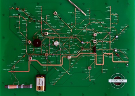
Radio Built From The London Underground Map

We love it when PCB artwork is actually artwork. Here’s one example of a radio whose layout mimics the map of London’s subway system.

The build is for an exhibit at the London Design Museum. They have an artist in residence program which allowed Yuri Suzuki time and resources to undertake the project. He speaks briefly about the concepts behind it in the video after the break.

The top layer of copper, and silk screen was positioned to mirror the subway lines and stops on a traditional transportation map. Major components represent various transfer hubs. In this way he hopes the functioning of the circuit can be followed by a layman in the same way one would plan a trip across town.

This may be a bit more abstract than you’re willing to go with your own projects. But there are certainly other options to spicing you track layout.

Continue reading “Radio Built From The London Underground Map”

Hackerspace Intro: Xin Che Jian In Shanghai

[youtube=https://www.youtube.com/watch?v=SGx5hm4jwNQ]
[Paul] wrote in to submit this video introduction to the Xin Che Jian hackerspace in Shanghai. It appears as though they have a fairly active space there, with several ongoing projects. They show off a range of things from an intelligent wireless power strip to aquaponics. The space seems to have the usual amenities such as project storage and a machine shop. The familiar sound of someone explaining that several of the tools are “almost working” reminds us that it is a small world, and we’re all pretty much the same.

Building A Passive 3D Projection System In Your Attic

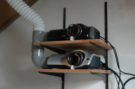
While the whole 3d movie/game craze seems to be ramping up, it really isn’t a new thing. We all recall those fancy red-blue glasses that were popular in theaters for a while, but I’m not talking about that. Passive 3d projection (using polarized glasses) has been around for a while too. Many people have figured out cheap ways to build these systems in their homes, but only recently have we seen media created for them in quantity.  Now that you can buy 3D games and movies at your local box store, the temptation to have a 3d system in your home is much higher.

Here’s a great read on how to put together a fairly simple projection system that uses two identical projectors with polarizing filters. Basically, all you need are two projectors, two filters, a screen, and the glasses. There are plenty of tips for mounting and setup in the thread to help alleviate any headaches you might encounter.

This system is primarily used with a PC, because it requires two video feeds to function. A cost breakdown might make you wonder why you wouldn’t just jump on amazon and get a 32″ 3d tv for under $400, but sitting in front of that giant screen might make you understand.

3D Printer Control For The Raspi

Instead of dedicating his laptop to control his RepRap all night, [Walter] is using a Raspberry Pi as an Internet-enabled front end for his 3D printer.

Before [Walter] got his hands on a Raspberry Pi, he set up his laptop next to his RepRap and let the machine do its work for hours on end. Obviously, this tied up his laptop for a while so when his Raspi was delivered he was eager to offload the responsibilities of controlling a printer to his new Linux board.

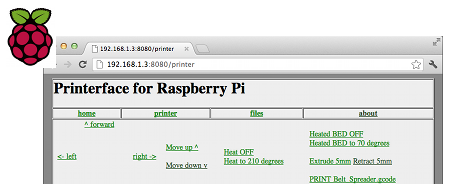
Right now, [Walter] has his Raspberry Pi set up as a web interface able to control his printer similar to Pronterface. We have to note that the Raspberry Pi isn’t driving servos or feeding filament onto the bed; those responsibilities are still handled by the RepRap electronics, but the ability to use a 3D printer over the web is still pretty cool.

[Walter] is putting the finishing touches on his 3D printer web interface, after which he’ll upload everything onto the git. Planned features for future updates include uploading gcode from the web and an option to connect a webcam for visual feedback when controlling a remote printer.

Video demo after the break.

Continue reading “3D Printer Control For The Raspi”

Hacking The Peggy

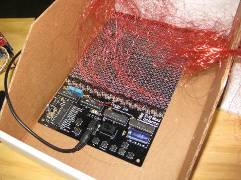
Evil Mad Scientist Laboratories received an email from someone who wanted to hack their Peggy kit. This LED matrix kit has been featured on Hack a Day in the past, and provides hardware to set up a 625 LED matrix.

This user built an external array of LEDs that they wanted to drive with the Peggy hardware. There are a few options for making this happen. The first one is to run wires from each of the 625 LED footprints on the board. Each has an anode and cathode, so that makes for a total of 1250 wires to run. It turns out that people have actually done this with the Peggy in the past, using very fine wire.

EMSL suggests wiring the rows and columns instead. This way, only one wire is needed for each row and column, allowing a 25×25 LED grid to use 50 wires instead of 1250. They also explain how to expand the grid to a 30×20 LED matrix. It’s a good explanation of how the kit works, and how it can be expanded.

Photo [oskay]

Measuring A Pulse With Infrared Light

The next time you’re unfortunate enough to make your way to a hospital, emergency room, or urgent care clinic, you’ll be asked to attach a small pulse monitor to your finger. The device the nurses clip on to one of your remaining digits is called a photoplethysmographic sensor, and basically it is able to read your pulse through reflected light. In the search to find out how these devices actually work, [Raj] sent in a great tutorial covering the theory behind photoplethysmographicy, and also built a simple device to detect a pulse without using a microcontroller.

These photoplethysmographic sensors operate by shining light into someone’s flesh – usually a finger or ear lobe – and recording the light reflected back to the source. The volume of blood in the finger will have an effect on the amount of light reflected back, and makes for a perfect way to automatically measure someone’s heart rate.

To build his device, [Raj] used a TCRT1000 reflective optical sensor. Inside this sensor is an infrared LED and a phototransistor. Of course with a finger over the sensor there is a ton of noise both from ambient light and the base rate of reflected light from a piece of flesh. [Raj] filtered this out, leaving only the small variations in the amount of reflected light, thus creating a very simple – and very inexpensive – electronic pulse meter.

Raspy Juice Gives You Serial Ports And Servo Control

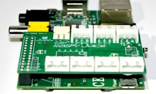
Up next on the continual march of expansion boards for the Raspberry Pi is the Raspy Juice, a board designed to break out the GPIO pins on the Raspberry Pi into servo, serial, and other miscellaneous connections.

The Raspy Juice features an ATMega168A microcontroller connected to the Raspberry Pi as an I2C slave device. Not only does the addition of a microcontroller add analog inputs to the Raspberry Pi, but also RS232 and RS485 serial connections, a real-time clock, and four JST plugs for hobby servos.

Because the Raspberry Pi can be powered from the GPIO header, the creator, [NTT] added a buck regulator so batteries or solar cells can be used to power the Raspberry Pi.

The Raspberry Pi is a terribly awesome robotics platform, but sadly limited by its capability to drive motors and servos natively. The Raspy Juice adds some much-needed capability to the Raspberry Pi, and we can’t wait to see a robot take its first steps with this expansion board.