IOS Terminal Debugging Tool

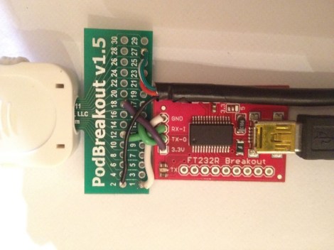
This is a simple iOS debugging tool that will take no time to solder together. There’s even a chance that you already have everything you need on hand. The hack simply connects an RS232-to-USB converter to a breakout board for an iPod connector.

The hardware is aimed not at stock iOS systems, but as an aid to those who wish to run alternative operating systems on them. When the OpeniBoot package is run on an iPod Touch or iPhone it enables a serial terminal on pins 12 and 13. The FTDI breakout board takes these as RX and TX and makes them available to your terminal program of choice via USB. Speaking of USB, you may already have noticed the black cable leaving the right side of the image. Using the terminal doesn’t limit your ability to use the device’s USB functions.

Art Controller: Relay Board With Switches For Timing

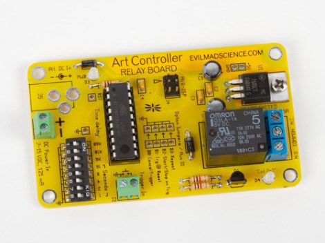
Meet the Art Controller, a new dev board available over at Evil Mad Scientist Laboratories. It provides a drop-in solution for switching higher voltage loads (but not mains). The thing we like most about it is the ability to alter a switching delay without reprogramming the firmware.

The board uses an ATtiny2313 for control. It’s fed regulated 5V power from the on-board 7805 linear regulator. The relay can handle a 24V DC or 40V AC load, which is targeted at an audience that needs electronic switching for art-related devices but doesn’t want the hassle of designing a circuit every time. This offers a single shot, or repeat action, with that bank of DIP switches selecting a delay from once every second, to every 31 hours. It can get its initial trigger from anything that can pull a pin low, like a button, or a coin acceptor.

Keep this in mind. The open source nature of the project means it could come in handy as a reference design.

Radio Built From The London Underground Map

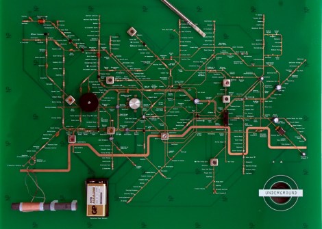
We love it when PCB artwork is actually artwork. Here’s one example of a radio whose layout mimics the map of London’s subway system.

The build is for an exhibit at the London Design Museum. They have an artist in residence program which allowed Yuri Suzuki time and resources to undertake the project. He speaks briefly about the concepts behind it in the video after the break.

The top layer of copper, and silk screen was positioned to mirror the subway lines and stops on a traditional transportation map. Major components represent various transfer hubs. In this way he hopes the functioning of the circuit can be followed by a layman in the same way one would plan a trip across town.

This may be a bit more abstract than you’re willing to go with your own projects. But there are certainly other options to spicing you track layout.

Continue reading “Radio Built From The London Underground Map”

Hackerspace Intro: Xin Che Jian In Shanghai

[youtube=https://www.youtube.com/watch?v=SGx5hm4jwNQ]
[Paul] wrote in to submit this video introduction to the Xin Che Jian hackerspace in Shanghai. It appears as though they have a fairly active space there, with several ongoing projects. They show off a range of things from an intelligent wireless power strip to aquaponics. The space seems to have the usual amenities such as project storage and a machine shop. The familiar sound of someone explaining that several of the tools are “almost working” reminds us that it is a small world, and we’re all pretty much the same.

Building A Passive 3D Projection System In Your Attic

While the whole 3d movie/game craze seems to be ramping up, it really isn’t a new thing. We all recall those fancy red-blue glasses that were popular in theaters for a while, but I’m not talking about that. Passive 3d projection (using polarized glasses) has been around for a while too. Many people have figured out cheap ways to build these systems in their homes, but only recently have we seen media created for them in quantity.  Now that you can buy 3D games and movies at your local box store, the temptation to have a 3d system in your home is much higher.

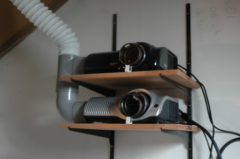
Here’s a great read on how to put together a fairly simple projection system that uses two identical projectors with polarizing filters. Basically, all you need are two projectors, two filters, a screen, and the glasses. There are plenty of tips for mounting and setup in the thread to help alleviate any headaches you might encounter.

This system is primarily used with a PC, because it requires two video feeds to function. A cost breakdown might make you wonder why you wouldn’t just jump on amazon and get a 32″ 3d tv for under $400, but sitting in front of that giant screen might make you understand.

3D Printer Control For The Raspi

Instead of dedicating his laptop to control his RepRap all night, [Walter] is using a Raspberry Pi as an Internet-enabled front end for his 3D printer.

Before [Walter] got his hands on a Raspberry Pi, he set up his laptop next to his RepRap and let the machine do its work for hours on end. Obviously, this tied up his laptop for a while so when his Raspi was delivered he was eager to offload the responsibilities of controlling a printer to his new Linux board.

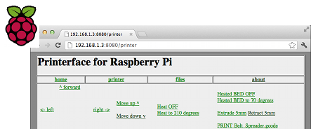
Right now, [Walter] has his Raspberry Pi set up as a web interface able to control his printer similar to Pronterface. We have to note that the Raspberry Pi isn’t driving servos or feeding filament onto the bed; those responsibilities are still handled by the RepRap electronics, but the ability to use a 3D printer over the web is still pretty cool.

[Walter] is putting the finishing touches on his 3D printer web interface, after which he’ll upload everything onto the git. Planned features for future updates include uploading gcode from the web and an option to connect a webcam for visual feedback when controlling a remote printer.

Video demo after the break.

Continue reading “3D Printer Control For The Raspi”

Hacking The Peggy

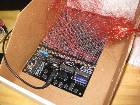
Evil Mad Scientist Laboratories received an email from someone who wanted to hack their Peggy kit. This LED matrix kit has been featured on Hack a Day in the past, and provides hardware to set up a 625 LED matrix.

This user built an external array of LEDs that they wanted to drive with the Peggy hardware. There are a few options for making this happen. The first one is to run wires from each of the 625 LED footprints on the board. Each has an anode and cathode, so that makes for a total of 1250 wires to run. It turns out that people have actually done this with the Peggy in the past, using very fine wire.

EMSL suggests wiring the rows and columns instead. This way, only one wire is needed for each row and column, allowing a 25×25 LED grid to use 50 wires instead of 1250. They also explain how to expand the grid to a 30×20 LED matrix. It’s a good explanation of how the kit works, and how it can be expanded.

Photo [oskay]