Summer And Tailgating DIY Projects Roundup

tiger-paw-cornhole

If you live in the Southeastern United States as I do, you’ve probably been enjoying a summer of grilling out and going to the beach or lake. You’re also may be getting ready to enjoy football tailgating season, especially if you attend or live near a college town. Here’s a couple of DIY items that should be welcome at any outdoor event you choose to attend.

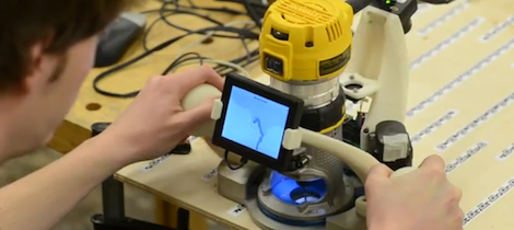
How to Make a Cornhole Board:

cornhole toss board

Although there are no LEDs or an Arduino on this one (we’d love to see your pimped boards in the comments), these instructions should work well for making your basic cornhole set. Of course you can always add some folding legs to it, but they fit together pretty well as is.  As for the paint, there are many ways to do this, but check out the pic after the break to see the laser-cut stencil that the Tiger Paw in the first picture was made from.  Thanks [Essam]!

PVC Ladder Toss Set:

ladder toss game PVC

These instructions should tell you all you need to make your own ladder toss (or whatever less-PC name you decide call it). As for the golf ball “bolas,” you’ll have to figure out how to put a hole in the middle of them. This technique (as seen in a links post earlier) should cover it, but best to be careful that you’re not plunging into a liquid-core ball. Eye protection is recommended.
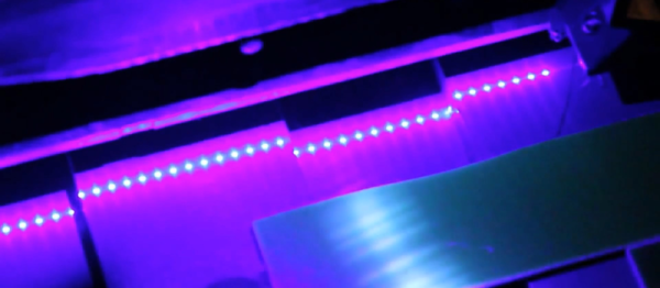
LED Glow Cubes:

solar LED glow cube

Although not a traditional tailgate item, these glowing solar LED cubes could serve as an alternative to the normal LED path lights. What’s in these instructions is how to simply take the parts source, a solar path light, apart and insert it into a translucent cube. We could see this made with several different colored LEDs and an Arduino for some other cool effects.  A logo of your favorite team could be added with a laser cutter or CNC router for tailgate use. Continue reading “Summer And Tailgating DIY Projects Roundup”

Robotic Hand With Haptic Feedback

While I was at Heatsync Labs in Mesa Arizona, [Nate] mentioned that he was really proud of helping someone build a robotic hand. I have tracked down that project because it looked pretty cool.

[Macguyver603] built this robotic hand that is controlled by a glove with flex sensors. He was originally going to 3d print the structure for the hand but the availability of the laser cutter allowed him to create something a that would be a little more structurally sound. Haptic feedback is supplied by vibrating pager motors that are triggered by sensors in the tips of the robotic hand’s fingers.

The total cost of the project was roughly $240, and there’s unfortunately no video. It did, however, earn him second place at the state fair!

Sound-o-Light: Simple And Interesting DIY Speakers

This is a great project for a slow afternoon, or a beginners introduction to DIY. [William] shows off a really simple speaker project that results in a light show as well as a decent enclosure. He’s using a PVC elbow to mount the speakers. They’re just glued in place. Below that, a section of clear tube allows for the lighting effects and a flange at the bottom supplies stability. For the lights, [William] opted to forego any complicated electronics and simply wired LEDs to the speakers themselves.

Admittedly we’ve seen more complicated systems in the past, but his results are quite nice and could be done pretty fast.

Largest CNC Router Is Controlled By Hand

Fresh from this year’s SIGGRAPH is a very interesting take on the traditional X Y-table based CNC machine from [Alec], [Ilan] and [Frédo] at MIT. They created a computer-controlled CNC router that is theoretically unlimited in size. Instead of a gantry, this router uses a human to move the tool over the work piece and only makes fine corrections to the tool path with the help of a camera and stepper motor.

The entire device is built around a hand held router, with a base that contains a camera, electronics, stepper motors, and a very nice screen for displaying the current tool path. After a few strips of QR code-inspired tape, the camera looks down at the work piece and calculates the small changes the router has to make in order to make the correct shape. All the user needs to do is guide the router along the outline of the part to be cut with a margin of error of a half inch.

You can read the SIGGRAPH paper here (or get the PDF here and not melt [Alec]’s server), or check out the demo video after the break.

Anyone want to build their own?

Continue reading “Largest CNC Router Is Controlled By Hand”

Southwest Tour: Heatsync Labs In Mesa Arizona

With temperatures rising to around 117degrees, we arrived in Mesa Arizona to visit Heatsync Labs as part of our Southwest Tour.  We have actually seen a tour of Heatsync in the past, and you should probably refer back to it for the quick run-through of the facility. When I was there, there was simply so much to see and talk about that the video ended up running over 10 minutes and I feel we barely scratched the surface of what was going on.

Continue reading “Southwest Tour: Heatsync Labs In Mesa Arizona”

Turning A 12 Year Old Mill Into A Modern Workhorse

Even though the Roland MDX-20 CNC mill fetched a pretty penny when it was first made available 12 years ago, there were a few features that made any builder lucky enough to own one scratch their head. The only way for a computer to communicate with this mill was through an RS-232 connection, and instead of a normal control protocol such as GCode, the Roland mill uses a very proprietary software package.

[Johan] fixed these problems and at the same time turned this wonderful machine into a tool for the 21st century. Now, instead of running a very long serial cable to his mill with a serial to USB converter at the end, he can just plug a USB cable into his mill with the addition of an FTDI USB to serial chip wired directly to the mill’s circuit board.

Stock, the Roland mill used a very strange proprietary communications protocol. [Johan] was able to reverse engineer this protocol by tracing out a few simple shapes and curves and taking a highlighter to the printout of the resulting file. Instead of the outdated software package that shipped with his mill, [Johan] can now export tool paths directly from his CAD program and send them over a USB cable.

It really is a shame such a nice machine like [Johan]’s mill suffered from the glaring shortsightedness of Roland executives 12 years ago, but at least now [Johan] has a machine that should easily last another decade.

Exposing PCBs With A Home Made Laser Printer

Making your own printed circuit boards – as useful as it is – is a pain. Using the very popular toner transfer method requires a dozen steps that have to go perfectly the first time, and milling boards on a CNC machine creates a lot of mess. The most industrious hackers are able to bodge up a direct-to-board printer from an old inkjet printer, but these builds are usually a little kludgy. [Tixiv]’s LaserExposer board printer is one of the first builds we’ve seen that does away with all the negatives of the other techniques of PCB manufacturing and turns making your own boards into a very, very simple process.

The LaserExposer uses photosensitive copper board, like many of the other PCB printers we’ve seen. Instead of printing out the board artwork to a transparency or mask, [Tixiv] used a 1 Watt 445nm blue laser with a hexagonal mirror to directly expose the artwork onto the board, line by line.

The entire device is built around an old flatbed scanner that slowly crawls over the PCB, exposing the traces of copper to be etched away. This required reverse engineering the mirror motor control board from an 90s-era laser printer and building a circuit to precisely control the timing of the laser. [Tixiv] eventually got everything working and after etching had some of the most professional looking home-brew boards we’ve ever seen.

[Tixiv] put up a demo video of his build (after the break, German audio, YouTube has captions…). Anyone have an old flatbed scanner lying around?

Continue reading “Exposing PCBs With A Home Made Laser Printer”