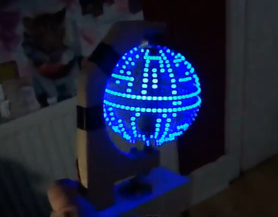
Building a Persistence of Vision globe is pretty awesome, but overlaying a Death Star pattern on the display takes it to the next level of geekery. Like us, [Jason] has wanted to build one of these for a long time. His success pushes us one step closer to taking the plunge and we hope it will inspire you to give it a shot too.
As he mentions in the beginning of his write up, the mechanical bits of these displays are really where the problems lie. Specifically, you need to find a way to transfer power to the spinning display. In this case use went with some DC motor brushes. These are replacement parts through which he drilled a hole to accept the metal axles on top and bottom. We hadn’t seen this technique before, but since motor brush replacements are easy to find and only cost a few bucks we’d say it’s a great idea.
The 24 blue LEDs that make up the display are all on one side of the PCB. They’re driven by an ATmega328 running the Arduino bootloader. [Jason] uses an FTDI adapter to program the chip. Don’t miss the video embedded after the break.


WOOOT. someone please invent a POV that doesnt flicker when video taped
Wow, seriously? Why not ask people to invent a monitor that doesn’t flicker when filed, or car wheels that dn’t look like they are spinning backwards at certain speeds. You realise that video is just sequential images right??
cause i dont care what car wheels look like or monitors, i want the youtube video of the pov death start to be SOLID
It’s all the camera’s fault, honest :) you wouldn’t believe all the messing about with camera settings I needed to get it to look even that good…
Professional video cameras (often?) have a variable frame rate control, to allow filming of monitors and such without the bright bars.
Oops, I also meant to mention that “newsrooms” on televisions also use either the variable frame rate to avoid the video monitors in the background (behind the talking head) from flashing and bright bars. A Time Base Corrector and/or a master sync may also come into play. Some of the “newsroom in the background” also just use painted glass to look like a bunch of monitors (low budget).
It’s called a Genlock. Synchronizes the monitor(s) and camera(s) so the blanking intervals aren’t seen by the cameras.
an old VCR head (or maybe a smaller rotating head, like a DAT) might be a good way to handle correctly the power and some communication with the “non-rotating” world.
Yeah.. how the hell to they connect those things? time for some reading :)
Search for ‘using vcr rotary transformer’.
Quite a few good POV projects with details for hacking the flying head(s) assembly.
You don’t “need” to find a way to transfer power into the rotating part. You could always use a small battery to blink the LEDs.
now with RGB LED’s you could also have the DeathStar explode in bright white/yellow/red after a few seconds!
When I saw the Earth display I thought, “If he had RGB LEDs in that thing he could plot satellite paths with it.”
http://www.youtube.com/watch?v=cQhBm_EgB0w
http://www.youtube.com/watch?v=ziD_1fVdDWQ
Whoa. That is truly Well Done!
@ JB – OK, that is officially THE BALLS!
Hehe… you asked for RGB… you got it! :D
Wow .. all that awesomeness and all anyone can comment on is the video flicker?
Nice build! Kinda bummed that after all that awesomeness of the board and layout the best you could come up with for a counter weight was to glue a couple of common, ugly, 1/4-20 nuts to the board.
Make one with RGB LEDs and animate the trench run and explosion of the death star.
With a little more work, I’m sure this could be adapted to work with continuous pulses over the horizontal “plane” (longitudinal) to create horizontal lines instead of discrete dots.
Varied brighnesses would be interesting also, although I’m not sure you could pulse PWM fast enough to achieve that given you’re already pulsing the LEDs fairly quickly to create the POV effect in the first place.
I guess PWM might work if the PWM clock was fast enough… only one way to find out! BTW the plotting is deliberately broken into discrete dots by turning all the LEDs off at every half pixel period – the reason is that the dots look better than streaks and give the fake impression of a higher resolution :)
Instead of adding a usless counterweight to the other side, why not add a second set of LEDs/driver and stagger them to get a better resolution.
To power the LEDs you could use the wireless power transfer circuit that’s been used a few times. A coil around the circumference of the spinning disk, and one in the base.
Or put an array of Schottky Barrier Diodes on the PCB and have them rectify a microwave beam aimed at the device. B^)
Reading up on slip rings and discovering rotary transformers, would anybody know (or have experimentally tested) the frequency response of the rotary transformers used in VCR heads? If it reaches in the 10-15MHz range the heads may actually be useable for 10BaseT.
High-frequency AC for power through a coil or two, 10BaseT (or other comm. standard / hack that works with galvanic isolation) and you have a system tat completely foregoes slip rings and can handle pretty huge RPMs.