Soldering Small Components For A Video DA

Video DA Board

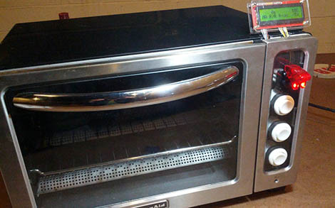
Video distribution amplifiers are used to amplify a video signal and split it into multiple outputs so multiple displays can be driven. They are also used to correct the gain of an incoming video signal. [Andrew] was having trouble with the video signal from an interferometer, and found the issue was caused by a low output gain. His solution was to build his own video distribution amplifier.

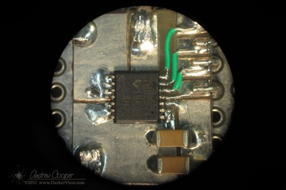
The THS7374 appeared to be the perfect chip for this application. It’s a four channel video amplifier IC, and only requires a few passive components to run. The only problem was the package: a 14 pin TSSOP with 0.65 mm pitch. Not fun to solder by hand, especially if you don’t have a PCB.

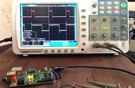
[Andrew]’s solution was to build his own breakout out of copper-clad board. He worked under a microscope and cut out a pattern for the part, then soldered 30 AWG wire to the pins to make connections. After cleaning off any copper that could cause a short, the board was working, and the video waveform looked great on an oscilloscope.

After testing, even more gain was needed. [Andrew] ended up cascading two of the amplifiers. This method of prototyping doesn’t look easy, but could be worth it when you need a single board.

Hack A Day On Fact Or Fiction With [Veronical Belmont]

Enjoy a fun episode of “Fact or Fiction” with [Veronica Belmont], with guest [me] from Hackaday.  The show “Fact or Fiction” generally takes some popular topic and talks to experts who can shed some light on the topic. They’ve had all kinds of intelligent people on, and also me.  If you watch a few episodes you’ll see that she tends to let people talk about the science for a bit, but inevitably veers over into “can we actually make this?”, which tends to elicit an awkward and somewhat humorous response from the person being interviewed, because most of the things they’re talking about are pretty outlandish, like portal guns.  I enjoyed the one about life on mars, especially when she asks the gentleman how accurate portrayal of martians in movies are, right after he explained that we’re looking microscopic things.

On a completely unrelated note, it is a very very small world. I ran in to [Veronica] at CES a few years ago and we found that both her and her husband both worked in the same office as [Phil Torrone] when Hackaday was just beginning.

Reflow Oven Courtesy Of Hurricane Sandy

2013-01-23-00.51.57

The Makerbar, Hoboken’s Hackerspace, was in desperate need of a reflow oven. Hurricane Sandy did a number on a whole bunch of household appliances, so when [Kush] saw a neighbor throw out a broken toaster oven, the Makerbar crew sprung into action.

The storm waters shorted the electronics board, fried the existing controls, and basically turned the oven into a metal shell with heating elements. It was the perfect platform for a toaster oven – every part that was going to be thrown out was already destroyed.

[Zach] over at the Makerbar ordered the Sparkfun reflow toaster conversion kit along with a few arcade buttons and set to work. After plugging the heating elements into the mains power to make sure they still worked, [Zach] attached these elements to the relay on board the controller. Three arcade buttons were wired up to the controller, and a whole bunch of code was written.

With the included thermocouple, [Zach], [Kush], and the rest of the Makerbar gang now have a very accurate and reliable reflow oven. There’s also settings for Sculpey clay and shrinky dinks, just in case anyone at Makerbar is feeling a bit creative.

Better PWM On The Raspberry Pi

pi

[Thomas] wanted to play around with a few high-power LEDs and a RaspberryPi. LED controllers usually require some form of PWM to change the brightness of a LED, and unfortunately the Pi only has one PWM pin. [Thomas] could have gotten around this with a custom chip or even an Arduino hanging off the Pi’s USB port. He opted to go with software-based PWM, and did so in a way that is far superior to bit banging a pin.

Conventional wisdom says PWM without a real-time operating system is dumb – right up there with starting a land war in Asia. Turning a pin on and off in a while loop will eat up all the processor power in the Pi, so [Thomas] looked for a better way to do things. He came across the ServoBlaster project by [Richard Hirst] that creates pulses of different lengths by playing with direct memory access; [Richard] created a circular buffer that is read every 10μs. With 2000 values in the buffer, he can control eight different pins with very little impact on CPU usage.

For [Thomas], though, [Richard]’s project wasn’t enough. It was originally written for servos and is only able to drive PWM pins up to about 12%. A quick rewrite of [Richard]’s code allowed [Thomas] to control eight pins with PWM varying from 0% to 100% – and be able to do other things with his Pi in the process.

[Thomas] now has a 40 Watt RGB LED powered by a Raspberry Pi burned into his retina, and the satisfaction of a really clever way of giving the Pi more PWM pins.