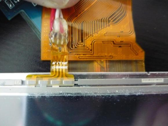
When [Andrei] first got his Raspberry Pi he wanted to make it a standalone computer right away. This means the normal input devices like a mouse and keyboard, but also some type of display. To avoid waiting for shipping he ended up using a cheap vehicle backup camera screen from the local big box store. It worked great, and recently he decided he would try to convert it to run off of 5V power to simplify his setup. While snooping around inside the device he discovered an unused resistive touch overlay and figured out how to get it to work.
What tipped him off is the small four-conductor connector which wasn’t hooked up to anything. He carefully soldered wires onto the flexible circuit traces, then generously covered them in hot glue to help prevent movement from breaking the rigid connection. To get this working you need to measure the resistance between the conductors. Most of the time we figure the RPi GPIO header can be used directly, but for this task an intermediary is necessary. [Andrei] went with a small Arduino clone board. A bit of trial and error was all it took to get the connections right and to iron out the code which translates the values into coordinates.


Love it…. Needs a 3 channel ATD, buys an Arduino
Back in my day sonny, we called them ADC’s Analog/Digital Converter,
no get off’n my lawn!
Now this is a hack :D
Good find!
This screen got mentioned on the Hackaday forums too with some more useful info:
http://forums.hackaday.com/viewtopic.php?f=4&t=2360
2-channel ADC is enough. No need to measure resistance, it’s a simple analog voltage that needs to be read.
The Raspi doesn’t have an ADC, so he needs to add another processor (ExtraCube) and an FTDI board…to use the touch screen
Isn’t there a one board solution? (for less than the combined cost?)
Not criticizing the builder, just curious…
I guess it depends on what he intends to use the Raspi for…
otherwise a Palm Tungsten from a second hand store would do as much in a lot less
space…
you could just use a 3.3v IO SPI adc but thats a little harder to program
Definitely yes, he could be using a Resistive Touch Controller from Analog Devives or Maxim, some thing like like U$2 or U$3 dollar, or maybe just a free sample.
But he still have credit for finding a fast solution right on hes bench, it still a hack.
The FTDI is just to program the extra processor, I don’t think it’s used in the final circuit. If he works with MCUs then he certainly had one anyway.
The XPT2046 (http://people.ece.cornell.edu/land/courses/ece4760/FinalProjects/f2012/hs734_ks834/hs734_ks834/XPT2046.pdf) is a cheap touch screen controller that uses SPI and an interrupt line.
Why did they bother putting in the touch screen if it wasn’t going to be used?
Maybe they were manufactured for a project that failed, so a manufacturer bought them up cheap and stuck them in a car-rear-view device. Or maybe due to fluctuations of the market, they happened to be cheaper than the ordinary ones the week the manufacturer bought them.
I’m guessing they also make a more expensive model that includes it. It’s often cheaper to manufacture if you change as little as possible between models. I remember modding an old bearcat scanner for 800 mhz. It had the same hardware as the more expensive model, but had certain features disabled so people would pay more for them.
I want the one that has a fire button.
Oh jeez. buy a 4 wire resistive driver board off of ebay, pkug it into the USB port and call it done.
Probably easier, and certainly more efficient from a software point of view, to use a microcontroller. Doesn’t have to be an Arduino, but if he had one lying around, since they’re basically the same thing as an AVR, with a bit of software pre-loaded. Cheap, simple, and can use whichever GPIO and serial connection that’s built-in to the chip.
No overhead for the Pi having to unbundle USB packets just to get at 2 bytes, no need for a USB port multiplier. And if he wanted to add some other bit of hardware to it, that could hang off the Arduino too, which should have a few pins left spare.
If the Arduino was expensive or difficult to use, that’d be different, but this seems about right.
I noticed this too on my display. I hadn’t had the time to look into it more, I believe there is a way to use the touch screen on the driver board, some extra un populated stuff.
“Arduino for blog cred”
Gotta love XKCD
there are many ways to skin this cat, of course a real touchscreen IC would’ve been cheaper than an arduino, wouldn’t have needed much in the way of drivers either if you pick the right ones. But as a method to get something working, this the project method is entirely valid and just as good, whatever works is the right way :-)
I’m more interested about getting the LCD itself hooked up. Any ideas, references?
Found the datasheet for the lcd
http://www.eleparts.co.kr/data/design/product_file/LCD/PDF/PT035TN23%20V.1%20Final-Spec%28V03%29%28TSP%290601.pdf
and I found a ttl serial interface on the board that communicates with the ntsc – lcd driver chip.
http://www.eevblog.com/forum/projects/searching-for-an-elusive-data-sheet-mst703-lf/?action=dlattach;attach=29778
From the looks of it. might be possible to have s-video, component, rgb, vga and maybe hdmi input. add to this tiny display :)