Power meters like the Kill-A-Watt are great for keeping track of energy usage, and are also very hackable. The Kill-a-Watt in particular puts out analog signals proportional to current and voltage, which makes it easy to interface with a microcontroller.
Although reading analog voltages is easy enough, [Kalle] found a cheap Chinese power meter that is even more hackable. These inexpensive power meters cost about the same as a first-generation Kill-a-Watt, but they directly stream out digital data. The power meter [Kalle] hacked has a non-US plug, but the meter is available from the usual suppliers (eBay, Aliexpress, etc) with a 3-prong US plug and 120v rating.
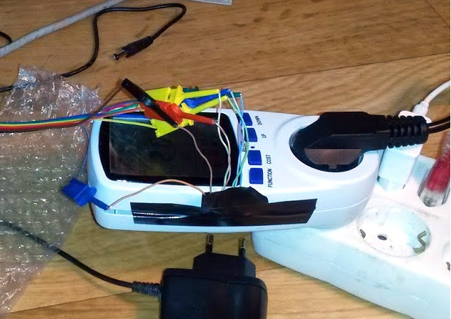
After breaking out a logic analyzer, [Kalle] discovered that the meter constantly streams voltage, current, and power data from the measurement board to the display board on a SPI-like bus. The ribbon cable inside the meter even has the clock and data bus lines clearly labelled. [Kalle] went on to reverse-engineer the protocol and write an Arduino sketch that parses the stream, making it even easier to integrate this meter into your next power monitoring project.


I’m impressed with his analysis of the SD1 and SD0 lines, I’ll have to look more into how MIS0 works…
Power meters like these do not have any isolations at its signals. Everything is live. May god help you if the place you are in don’t have proper wiring. (non-polarized outlets without a proper ground). This is when Bluetooth or wireless connections is essential for safety.
The signals are referenced to the Neutral. Things like your PC case/ground are reference to Earth ground. The two might or might not be at same potential. Laptops these day are not even grounded. Have to be carefully when you are hooking stuff up to PC for debugging/testing/programming.
A lot if Swedish hacks lately (including this one). I guess this is what’s standard in most countries, Sweden included:
* Non-polarized outlets.
* Neutral and ground is tied together the first thing that happens when it enters the house.
How is this improper?
Not knowing your local electrical code, I cannot make the comment. However that does sound like it is a bad practice as the Earth ground should be connected to a proper ground point at the electrical box. The Earth ground is supposed to protect you from electrical shock if there is a leak on the wiring. So the Earth ground should be at same potential as you the human would likely to be at and should not be a point at the Neutral.
Since the Neutral wire is supposed to carry the load current for return path, the I*R drop would cause a voltage along the neutral wire. While it might be a nominal few volts difference between that and Earth ground due to a heavy load on the circuit, that is not good enough for grounding. (I don’t even want to think about what happen to the neutral during electrical fault before the fuses blow.)
Old wiring (in old country or new), coupled with ungrounded 2 prong with a cheater plug to turn it into a 3 prong or inproperly wired outlet… There are so many things that can go wrong. I have seen a lot of places with bad wiring in my years renting/subletting in my poor student days. Lot of owners who think they can use a screw driver knows about electrical code. :P
Oops, you’d better tell the entire UK population that they have it wrong. (For reference, your assertion “Earth… should not be at Neutral [potential]” is a complete load of tosh).
One potential problem with connecting Earth to Neutral is that in case of a break in the Neutral wire, the entire case may effectively be coupled to the Line voltage.
If there is a fault at the upsteam side i.e. your local power distribution that raise the neutral potential, does that UK standard protect you when you touch the metal surface of an appliance?
http://www.emfs.info/sources/distribution/uk/ explains it quite nicely.
That links shows something slightly different that your over-simplified blanket statement about UK systems for all. What you claim is different enough that it makes a difference.
As always, there should be *separate* Earth ground vs neutral wires running in your house to the outlets. When I talked about *old* houses, bad wiring and cheater plugs, those Earth grounds do not even get routed to outlets. Don’t misread what I said to something else.
There are houses with PME and also houses with their independent Earth ground connections in your link that are not directly connected to Neutral. I would feel safer to have additional Earth ground connection *at my house* than one that relies on Neutral connection somewhere in the local power distribution on the street. The one at my house would be closer to what I am at when I touch the metal case of a “grounded” appliance.
http://en.wikipedia.org/wiki/Earthing_system
Most modern homes in Europe have a TN-C-S earthing system. The combined neutral and earth occurs between the nearest transformer substation and the service cut out (the fuse before the meter). After this, separate earth and neutral cores are used in all the internal wiring.
Note: they said about “modern” homes.
You need to read what I wrote again, Sweden uses TN-C-S which in practice means that the combined neutral and ground (called PEN) comes into the house, and is then split into neutral (N) and ground (PE) the first thing that happens (most importantly before whatever this is commonly referred to in English http://en.wikipedia.org/wiki/Residual-current_device ). This is what I meant by “Neutral and ground is tied together the first thing that happens when it enters the house.” Obviously, there are separate wires for neutral and ground to each outlet.
Jack Kelly had a lucky escape trying something similar. He was using a bus pirate to sniff the SPI bus of an IAM (a wireless appliance monitor), and managed to blow up his laptop and the buspirate. He documented what happened, so others can avoid doing the same: http://jack-kelly.com/blew_up_my_laptop_sniffing_spi_bus_of_iam
Good point about isolation, but there a lot of safe options besides wireless connections. And trying to reverse engineer an unknown signal over wireless would typically be impractical.
Other options:
1) Put the device under test on an isolation transformer. Or variac.
2) Don’t have either? Build one from two matched step-down transformers, back-to-back; converting 120VAC -> 12VAC -> 120VAC for example.
3) A UPS, when *unplugged* and running on battery, is also fully isolated. Or a battery and inverter.
4) And of course there’s optoisolators. The signals coming from this power meter are slow enough you don’t even need to worry about opto speed, any ol’ optos will do. If it were running SPI at Mhz speeds, opto selection would be more critical.
A variac IS NOT AN ISOLATION DEVICE! Know your transformers, your life can depend on it.
Oops, you’re right. Scratch the variac off the list.
To be fair, isolated variacs do exist. However, most I’ve seen are just autotransformers.
Knowing how badly the usual “open source” circuits/layouts I have seen from webpages to pcb, I do not consider that using opto-isolators are safe for the copy-paste clueless to power crowd. Wireless is certainly an attractive and less accident prone for that target group. Do the average “Arduino” here know the proper creepage distance layout and know enough to not run tracks between the opposite sides of a opto or know about current transfer ratios in the datasheet? I think not.
Well the average “Arduino” probably wouldn’t be able to reverse engineer an undocumented bitstream either.
But let’s say you have an arbitrary line-powered and unisolated device you want to hack. You’ve identified what are likely data lines. What you don’t know is whether they’re serial, SPI, I2C, or some proprietary format. You also don’t know bitrate, could be anything from 1200 baud, to SPI in the Mhz. And you won’t know until you hook up a signal analyzer, but you’re saying it should be hooked up *wirelessly*.
Ok, so how do you do that? Exactly what device or method do you propose that will transmit multiple digital channels, with unknown protocol and bitrate, *verbatim* to your signal analyzer for proper analysis?
Use a USB analyzer, plugged into a laptop running on battery, and don’t touch anything while the circuit is plugged in. Alternatively (or in combination), use an isolation transformer on the mains side.
Have you not heard of USB isolators, isolation transformer, scopes that runs on battery powert? There are tons of these type of equipment for professionals that works with power electronics. Just that you never thought about them do not mean they don’t exists.
There are even things that jump starts your car or let you run small appliances off its internal battery+inverter from hardware store. http://www.homedepot.com/s/portable%2520power?NCNI-5
Safety is my point here NOT try to tell you how to haxor your tech. These type of smart pants questioning do not let you work safe and only piss off others that are trying to help you.
If you don’t know how to do that safely, don’t try it. If you can afford fancy toys that you named, then you really should value your life…
Yes, I have heard of them. In fact I’ve already listed similar options. But up until now, you’ve talked about nothing but wireless isolation:
“This is when Bluetooth or wireless connections is essential for safety.”
Even to the point of shooting down other options:
“I do not consider that using opto-isolators are safe for the copy-paste clueless to power crowd. Wireless is certainly an attractive and less accident prone for that target group.”
Pushing wireless so hard suggests you actually have knowledge of some wireless device or method that will allow one to safely (in your opinion) repeat what was done in this hack; to reverse engineer a digital bitstream on multiple wires, with unknown protocol and bitrate. If so, I am genuinely interested in its existence. If not, you’ve been talking nonsense for your first two posts.
Considering that you now have nothing to say about wireless, have become defensive and insulting, and are falsely claiming you’re not telling people how to do stuff (you were – WIRELESSLY!), it appears to be the latter.
>4) And of course there’s optoisolators.
Opto-isolators are *slow*;… The average ones have propagation delays of 10us (if not tens of us).
and then you said:
>Ok, so how do you do that? Exactly what device or method do you propose that will transmit multiple digital channels, with unknown protocol and bitrate, *verbatim* to your signal analyzer for proper analysis?
Well even if you use an opto-solator, it won’t help you with that UNLESS you already know that the signal is slow and more forgiving. So that is just pointless noise.
Like I said… MOST people in the “open source” crowd do not know how to use opto-isolator *correctly* and it is a false sense of security to have them in a circuit.
I have only mentioned wireless once here. Every other thread in this discussion, I have mentioned a different way of protecting yourself. – GFI, working with 12V transformer, battery.. Read the time stamps.
This is getting outside of technical discussion… So no point of going further.
October 22, 2014 at 7:06 am – At least use a ground fault interrupter upstream as a backup
October 21, 2014 at 9:59 pm – You can do a lot of debugging even if you were to run the meter on 12V AC from a transformer (add battery to run the logic stuff). Only when debugging is done before you go live.
—-
October 22, 2014 at 12:53 pm <– That's when you said:
. But up until now, you’ve talked about nothing but wireless isolation:
Just because you *think* that you can hack/hex low voltage DC circuits doesn’t mean that you know about safety rules for mains… Too many monkey see monkey do crowd on the interweb. They think they are l337 after watching some utube video of someone (that may or may not be qualified) doing dangerous stuff.
We have people that deals with safety and power even when we have a team of senior digital engineers when we design products at places I worked for. Just because you have knowledge in one domain, do not imply you know it all. Know thy limits and respect thy live circuits…
At least use a ground fault interrupter upstream as a backup for other isolation measures when you must poke/hack around live stuff. They are not even expensive.
FYI The original power meters do not have any external (unisolated) connections, so they pretty much do all kinds of short cuts to lower the cost because they don’t have the *same* safety concern when you add the external interface. That is assuming that made in China stuff actually passes safety standards. Typically they have a shunt resistor between neutral to sense load current (with an opamp) and a voltage divider on the hot wire for the input voltage. Last thing you want is to somehow connect that neutral to an Earth ground between the logic analyzer dongle, to USB cable to PC to power ground to PC power supply Earth ground.
You can do a lot of debugging even if you were to run the meter on 12V AC from a transformer (add battery to run the logic stuff). Only when debugging is done before you go live.
Also previous HaD article for using wireless board to FLASH uC.
A safer method would be to point a camera at the display, and write a program to recognize the digits.
Even worse he was using a cheap Logic rip-off that probably had zero protection or isolation on the inputs. Nice screenshots of his pirate software too.
No no no no NO! – Kids, do not replicate this – Sniffing live circuits like that is just an accident waiting to happen :/
Made my palms sweaty when I read that they connected the cheap usb analyser to their mains powered test circuit. No no no. This is how you get killed.
Needs more Arduino :P
anybody got a good clear PCB picture of that meter? the one with actual ADC/SPI IC?
I opened 3-4 models of these meters(none shown here) and they all used something similar to this for measuring: http://ww1.microchip.com/downloads/en/DeviceDoc/22025C.pdf
There are many similar, pin and function compatibles, IC’s like this.
I think it is simpler to use an IC like this than do all the complicated stuff in software on a micro(you also need a rather expensive micro to reach 16 bit ADC).
http://www.strasil.net/index.php?text=wattmetr / digital wattmeter with optical isolated output which can anyone build at home. /use translator
Hi,
some bytes have to indicate the phase difference between voltage and current. Otherwise the meter will measure the apprent power, I think that it measure the active power (the hacked meter is inspired to compute energy costs and it has no sense compute energy costs using apparent power value). In AC the power formula is P=V * I * cos(phi)
A way to discover the phase byte cold be to compare measurement between a resistive load (solderong iron) and an inductive load (flurescent lamp with starter and reactor and without power factor correction capacitor. Connecting and disconnecting the capacitor you could see changes on the phase and also in current and apparent power, but active power remain the same). Phase angle (phi) could be positive or negative depending on nature of load (mainly inductive or capacitive).
Hi!
Good thing my computer didn’t decided to blow up while doing this… Actually I tested the setup on an old crappy laptop before I hocked it up to my PC to “make sure” nothing was going to fry my computer… Little did I know that it used Neutral as GND.
I updated the blog-post with an safety-hazard text!
I wonder why nothing happened? Could it be that the computers ground also became same as neutral? (time to take one step back from the computer chassis then ;)
The good thing is that I no longer have to use this setup… I have the working code, and can in the future connect it to the computer via nRF2401.
Happy programming
/Kalle
FYI: This is what they typically have inside those Kill-a-watt and thier knock offs.
http://www.mikesmicromania.com/2013/03/kill-watt-circuit-analysis.html
no, this is couple of years old analog design
new ones use dedicated ICs
but they would still have the same way of referencing non-isolated signals to neutral which has safety issues when you try to hack on some kind of non-isolated interface.
Interesting, but I am a bit skeptical about the quality of the cheap Chinese instrument like this when it comes to accuracy. I have a cheap German one that cannot even measure a power consumption of my settop box – it shows constantly changing random numbers.
The cheap German power meter probably shows constantly changing random numbers because the load is too small. Every kind of meters, cheap or super professional, are less precise as the measure moves away from the full scale value and very unreliable when the measured value is near the start of the scale. There is a solid mathematical proof to support this.
Even though it is Chinese and cheap, I’m pretty sure that it measures the active power and, in the midst of the data, there is also the phase angle or power factor value.
But there is a very simple test to discover if the meter measure active or apparent power:
– Take a fluorescent neon lamp (with traditional reactor)
– Measure current and power shown by meter.
– Remove the power factor correction capacitor and measure another time.
– The current has to increase. If it does’t happens the measure is wrong.
– If the power is the same, or changes very little, the meter is measuring the active power and somewere there is the value of power factor (or phase angle).
Example using 36W neon lamp:
normaly power factor of this lamp is about 0.55 and 36W is the active power.
P = V * I * cos(phi) -> 36 = 230 * I * 0.55
I = 36 / (230 * 0.55) = 0.285A
Now the apparent power is P = V * I -> P = 230 * 0.285 = 65,55 VA
A big diffrence……..
Using the power factor correction capacitor the power factor is 0.9 so:
P = V * I * cos(phi) -> 36 = 230 * I * 0.9
I = 36 / (230 * 0.9) = 0.174A
And the apparent power…. P = V * I -> P = 230 * 0.174 = 40,02 VA
that It’s different from active power….
A cheap PC power supply has a power factor around 0.65 / 0.7 and depend on load.
High-end PC power supplies have an automatic power factor correction system that insert inductive or capacitive elements to keep power factor near 0.9 / 0.95
according to Julian Ilett this one is ok and goes down to below one wat
https://www.youtube.com/watch?v=L2js9ZJ5zHs
Oh dear. Don’t do this without galvanic isolation on the data lines. It could potentially kill you, and/or your PC and equipment.
The “local” DC ground inside the double-insulated plastic case of the meter may be connected to the mains neutral pin… or it may be connected to the mains active. It makes absolutely no difference as far as the transformerless power supply inside the device is concerned… until you crack the case open and connect that “ground” (which is actually 240VAC relative to mains earth) to ground on your equipment or your PC without understanding what’s going on.
If they use low-power powersupply from capacitor and resistor, its GND connected to neutral and relatively safe until someone make mistake and swap just two wires somewhere…
Update:
I now have a working setup where the energy meter is completely wireless with an Arduino mini pro 3,3V and a nRF24L01+ module, transmitting the data to the computer!
/Kalle
Did you ever get your unit to work with your ESP8266? I’m about to embark on this path with your code and adapt it to the esp8266 and add a relay to the circuit so that I can also remotely turn the outlet on and off as needed (using this to power a pc in a remote location where i’ll need the ability to hard power cycle the machine)
i’m wondering specifically if you ever got it to work using the 3.6v battery leads and what size of a capacitor you used to do so for the wifi transmission signal.
Have 3 of the same meters running with a single ESP-07 sending MQTT data (Voltage/Power/Kwh) to my broker. Works great for several months now.
Been planning on doing this too, got couple of ESP12 around. Do you have any more details on your setup? I was wondering about the power supply, it looks like the onboard circuit won’t provide enough power for the ESP while transmitting (~100mA) and the regulator (75L05) is only rated up to 100mA.