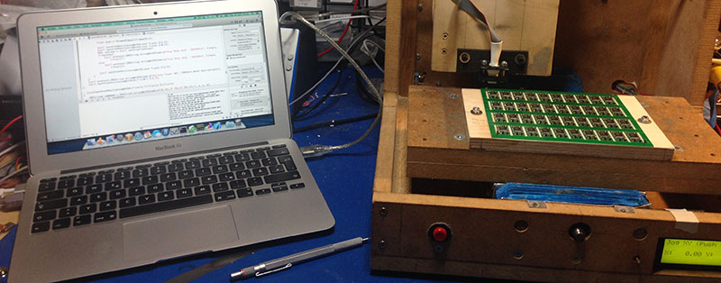
[Eberhard] needed to flash several hundred ATMegas for a project he was working on. This was a problem, but the task did have a few things going for it that made automation easy. The boards the ‘Megas were soldered to weren’t depanelized yet, and he had a neat and weird bed of nails programming connector. There was also a CNC machine close by. This sounds like the ideal situation for automation, and it turns out the setup was pretty easy.
The boards in question were for FPV/radio control telemetry adapter and thankfully the assembly house didn’t depanelize the 40 PCBs on each board before shipping them out. A very cool ATMega flashing tool handled the electrical connections between the computer and the microcontroller, but a real, live human being was still required to move this flashing tool from one chip to the next, upload the firmware, and repeat the process all over again.
The solution came by putting a few metal pins in the bed of a CNC mill, 3D print an adapter for the flashing tool, and writing a little code to move the flashing tool from one chip to the next. An extremely simple app takes care of moving the programmer to an unflashed chip, uploading the firmware, and continuing on to the next chip.
There’s still some work to be done that would basically tie together the Gcode and AVRdude commands into a single interface, but even now a complete panel of 40 PCBs can be programmed in a little over 10 minutes. You can check out a video of that below.


The video says that the flashing takes “about a minute. So I guess a full panel of 40 boards will take abut 40-60 minutes – not 10 minutes as stated above…
Cool hack anyways. ^_^
From the linked article: “[Update: after changing some default settings in avrdude, the time to flash a chip is down to 15 seconds…]”
It would be neat if all the AVRs could be ganged up with a few traces that all come together to the edge of the board, and are broken when depanelized.
Crazy but I had exactly the same idea after watching the video… :D
its a pretty common thing to do, as well as a board edge connector that you can break off later.
he is a recent example i did (pci-e connectors are cheap:)
https://static.hackaday.io/images/2146901411181973397.JPG
Wait, do I see two LEDs directly connected to mains with only a single resistor in series ?
And what is wrong with that? A LED flickering at 60hz (or 50) will look fine. If you’re concerned about safety there is nothing “safe” about this layout. Just don’t touch it when its plugged in.
Other than being power inefficient, as it dissipates most of the power as heat through the resistor, AC mains is surely above the breakdown voltage of every LED, personally I would put an 1N4148 in antiparallel with the LED just to be on the safe side…
had similar thought. Could have saved a lot of time to have a row of them connected to the break away with card edge connector. Mux them or make a gang of programmers to program a row at a time.
Since you already making PCB panels with uC, just set aside some and reuse them as the programmer.
Guess it just matters if time or money is the objective here. Over time, if this is something that gets mass-produced, this solution could end up saving quite a bit more money by getting more of the devices on a panel. If the programming time is an issue, could still gang the programmers on the CNC.
In very large scale, you’d get the IC manufacturer or disty to program chips before soldering, or with bed of nails / flying probe, whichever’s cheaper. So the OP’s scheme is in the spirit of something frequently done in mfg.
Unless you don’t trust someone in china with your firmware.
At the time I designed the PCB, it wasn’t clear, that there would be so many of them. So the panelizing was done by my PCB manufacturer. For one reason, because it was my first “mass production” PCB and I didn’t have experience with panelizing PCBs at all. So I thought, it would be best to leave the panelizing to the manufacturer instead of possibly sending design files back and forth until I get it right. The other reason, I didn’t put too much thought into additional traces on the panelized board for programming the ATMega was, that (as mentioned above) I thought there might be 100 or 200 of them. So it didn’t make much sense to put much time in the panelizing process.
This is where JTAG would come in handy.
Why?
to answer that question you need to learn what JTAG is
hint: token ring
Very neat solution. Might be a good idea to do a quick test while he is at it. ;)
How on earth does it take that long to flash the MCU? It takes my computer about 5-10 seconds to flash an ATMega328, and that’s with a cheapo AVR Dragon…
without verify…
The programmers vary widely so who knows.
I know one thing stay away from atiny stuff 5min + on an atmegas 328. while the mkII takes 15sec or so
add -b2 to the avrdude command and it will go much quicker.
Software. The article said a change in command got the flashing speed down to under 15sec
From TFA: “The recommended method is to use a 2nd-order Butterworth Low-Pass filter (considering the cost and performance) to restrict the signal in the audible range. In my case, I designed it for a cutoff frequency of 8KHz because my wave files are of 8K sampling rate. Also my pwm switching frequency is only 37.5KHz at 9.6MHz internal clock, so it is always better to keep the cutoff frequency far less than the switching frequency to make it more power efficient and to reduce the EMI. ”
Why does PWM output filter cut off at (approximately) sampling rate frequency? Isn’t that too high? The signal shouldn’t have any information content above half of the sampling rate frequency anyway.
your files have a 8K sampling rate, so the cutoff should be at 4K instead to avoid frequency aliasing, right?
I’m a bit confused as to what this connects to. It looks as if the comments belong to another article. What do wave files have to do w/ programming MCUs?
FWIW Aliasing is an ADC input problem. You need -6 dB amplitude for every bit in the ADC when you reach Nyquist. That requirement can be met by having many poles or setting the corner frequency several octaves below Nyquist and using fewer poles. One can make steeper skirts, but that leads to other problems with phase delay and ringing.
For DAC output, you’re trying to suppress harmonics generated by the steps from one sample to the next. As noted though, the input at 8 ks/s is band limited to 4 KHz, so that would be a better choice of corner frequency. The resulting constraint is similar. But in the ADC case, the noise from aliasing shows up at low frequencies. In the DAC case the noise shows up at high frequencies.
Analog filters are not magical brick walls as their gain start to drop even before cut off frequency (-3dB for 1st order, -6 for 2nd etc). So if you want a flatter frequency response, you want to move the f0 a bit higher.
Having said that, I don’t think it need to be that high.
A useful addition would be for it to make a physical mark on the board after each successful program operation.
Re.the speed – problem is a blank AVR clocks at 1MHz and programming clock needs to be slower than that (don’t recall the ratio- I think / 2or /4) the key trick is to preprogram the config fuses first to get the higher clock rate, then crank up the programmer’s SPI rate. This makes a massive difference to programing time.
Ok toss that up on my wishlist of reasons I want a CNC at some point (hopefully in the not terribly distant future) :D
Tho I’ll be honest the precise measurements required always stress me out, probably because I have next to zero experience on the subject.
Well, if your build has an LED connected to the uC (many times it’s true). You can make a firmware that checks the flash (there is a project on AVR Freaks where a uC uses CRC16: http://www.avrfreaks.net/projects/crc-16-tiny85-flash-image ), so the check could be done without the flasher, and you can see if the programming failed (by not seeing the blinking LED or something like that).
Since GND, VCC, MOSI, SCK and RST can be connected together (with some added electronics if you need to drive a lot of devices), you can flash them together if you can make the board to be broken into separate pieces after flashing.
Cool hack btw.
couldnt you just parallel all the flashing pins and flash the chips in 1 big shot?
Depends on the device. Flashing is not a one-way communication stream. Unless the protocol is designed to take into account communicating with multiple devices (my guess is AVR’s ISP is not) then you’re not going to be able to do this as all devices will shout at once.
These days I’ve switched to using USB microcontrollers with bootloaders. Hook them all together in a hub and run a batch script that flashes them and reboots them so they are no longer sitting in a boot loader state, rinse repeat until no USB devices with the PID in question remain.
I guess it would be a problem to verify the flashed firmware with such a set up. And I definitely want to verify the chip after flashing!
While this is a neat build, I have to ask the obvious – won’t Atmel supply the chips pre-programmed, if you’re doing that many? I know that Microchip will, with their PICs, and I’ve seen some people get as low as 100 chips from them, ready programmed.
I always thought that soldering temperatures were bad for data stored in flash. OTP parts wouldn’t matter, but for floating-gate FET cells, flashing before soldering would lead to reduced data longevity. I have no idea how severe this effect is, but I always thought that was the logic to programming after assembly even when other options are available.
If that were a problem, you could make your firmware reflash itself the first time it’s run! :P
Yes, just talk to your distro and they can get them to you pre-programmed.
As said before, the first batch of PCBs was only 200 parts. I doubt, that AVM does any pre-flashing with such low quantities (that seems to be different with Microchip’s PIC).
And I definitely wouldn’t give the firmware to any arbitrary Chinese 3rd party service provider.
And finally, I really needed the extra time for completing the firmware during the PCBs were already in production.
neat! i for one welcome our robot programming overlords.
BTW a few years ago a guy in Hungary built a robot for PIC flashing (mostly from salvaged parts)
http://www.astlab.hu/robot/robot.html (page in hungarian)
At the bottom of the page, you can see a video as well.
nice music choice in that video clip :))
cool contraption, could be a modern art piece in its own
By the way, I’ve got the same “socket tool” from HobbyKing. It’s good for the atmega8’s on the BLDC motor controllers and other devices in RC. I’d love something similar for the Atmega328s in the cheap arduino pro mini clones, has anyone seen this being sold anywhere online? They are smaller than the atmega8s.
socket tool? can you give me references about socket tool i’ve been learn for put on my web http://www,tentang-android.com thanks andrews