TRINKET EDC CONTEST DRAWING #5 RESULTS

The final random drawing for Hackaday’s Trinket Everyday Carry Contest was held tonight, and the winner is [flaming_goat] with Trinket Pocket IR Analyser/Transmitter!

ir2
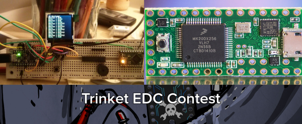
In addition to having an awesome username, [flaming_goat] loves IR protocols. Trinket Pocket IR Analyser/Transmitter is a standalone device to read, analyze and transmit Infrared (IR) signals. The IR portion of the project is handled by a Vishay TSOP38238 (PDF link) The 382 series is a 3 pin module. It comes in several variants, each tuned to a specific carrier frequency. The 38238 will decode IR signals at 38 kHz.

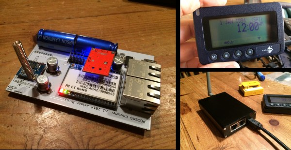
The demodulated IR signals are fed into the Pro Trinket, where they can be analyzed. Data is either sent through the serial terminal or displayed on the on-board 1.44″ TFT LCD. Source code for the whole project is up on [flaming_goat’s] GitHub repo.

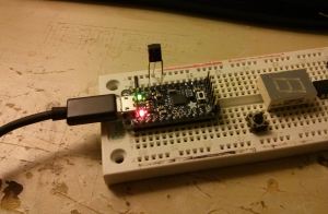
[flaming_goat] will be receiving a Teensy 3.1 and an Audio+SD adapter from The Hackaday Store. If the Pro Trinket is a gateway drug, then Teensy 3.1 is the hardcore stuff. Powered by a Freescale Kinetis ARM Cortex M4 processor in a tiny package, the Teensy 3.1 packs quite a punch. You might think all that power would mean complex tools, but Teensy 3.1 is still easy to program using the Arduino IDE. The Audio+SD adapter board gives Teensy 3.1 the ability to create some pretty decent audio, thanks to the Teensy Audio Library.

This was the last weekly drawing for the Trinket Everyday Carry Contest, but there is still time to enter and win the big prizes! The deadline is January 3 at 12am PDT. That’s just about 3 days to enter – so procrastinators, get in the game!

Flashing Chips With A CNC

[Eberhard] needed to flash several hundred ATMegas for a project he was working on. This was a problem, but the task did have a few things going for it that made automation easy. The boards the ‘Megas were soldered to weren’t depanelized yet, and he had a neat and weird bed of nails programming connector. There was also a CNC machine close by. This sounds like the ideal situation for automation, and it turns out the setup was pretty easy.

The boards in question were for FPV/radio control telemetry adapter and thankfully the assembly house didn’t depanelize the 40 PCBs on each board before shipping them out. A very cool ATMega flashing tool handled the electrical connections between the computer and the microcontroller, but a real, live human being was still required to move this flashing tool from one chip to the next, upload the firmware, and repeat the process all over again.

The solution came by putting a few metal pins in the bed of a CNC mill, 3D print an adapter for the flashing tool, and writing a little code to move the flashing tool from one chip to the next. An extremely simple app takes care of moving the programmer to an unflashed chip, uploading the firmware, and continuing on to the next chip.

There’s still some work to be done that would basically tie together the Gcode and AVRdude commands into a single interface, but even now a complete panel of 40 PCBs can be programmed in a little over 10 minutes. You can check out a video of that below.

Continue reading “Flashing Chips With A CNC”

New 3D Printing Technique – Friction Welding

Even though 3D printers can fabricate complex shapes that would be nearly impossible to mill, they are not well suited to designs requiring bridging or with large empty spaces. To overcome this, [Scorch] has applied an easy plastic welding technique that works with both ABS and PLA. All you need is a rotary tool.

Friction welding” is the process of rubbing two surfaces together until the friction alone has created enough heat to join them. Industrially, the method is applied to joining large, metal workpieces that would otherwise require a time-consuming weld. In 2012, [Fran] reminded us of a toy from decades ago that allowed children to plastic weld styrene using friction. This modified method is similar to stick welding in that a consumable filler rod is added to the molten joint. Inspired by our coverage of [Fran], [Scorch] experimented and discovered that a stick of filament mounted into a Dremel works just as well for joining 3d prints.

That is all there is to it. Snip off a bit of filament, feed it into your rotary tool, and run a bead to join parts and shapes or do repairs. Friction welded plastic is shockingly strong, vastly superior to glued plastic for some joints. Another tool for the toolbox. See the videos below for [Scorch]’s demo.

Continue reading “New 3D Printing Technique – Friction Welding”

Retrotechtacular: Principles Of Hydraulic Steering

Have you ever had the pleasure of trying to steer a one-ton pickup from the 1940s or wondered how hard it would be to turn your car without power-assisted steering? As military vehicles grew larger and heavier in WWII, the need arose for some kind of assistance in steering them. This 1955 US Army training film handily explains the principles of operation used in a hydraulically-assisted cam and lever steering system.

The basic steering assembly is described first. The driver turns the steering wheel which is attached to the steering shaft. This shaft terminates in the steering cam, which travels up or down along the camshaft depending on the direction steered. The camshaft connects to the steering shaft through a spline joint, which keeps the travel from extending to the steering wheel. The steering cam is connected to the Pitman arm lever and Pitman arm shaft. Movement is transferred to the Pitman arm, which connects to the steering linkage with a drag link.

The hydraulic system helps the Pitman arm drive the linkage that turns the wheels and changes the vehicle’s direction. The five components that comprise the hydraulic system use the power of differential pressure, which takes place inside the power cylinder. The hydraulic system begins and ends with a reservoir which houses the fluid. A pump driven by the engine sends pressurized fluid through a relief valve to the control valve, which is the heart of this system.

Continue reading “Retrotechtacular: Principles Of Hydraulic Steering”

[Sophi Kravitz] Joins The Hackaday Crew

Please join us in welcoming [Sophi Kravitz] to the Hackaday crew. She is coming on board to crank on the 2015 Hackaday Prize. You may remember a post from a few weeks ago when we were in search of a person with a skill set that could only be described as mythical. [Sophi] jumped at the chance and it is immediately clear that she belongs here.

[Sophi] walks the walk, and talks the talk. She’s an EE and has worked with art installations, built props and FX for movies, and tackled jobs that some might consider ‘more serious’ engineering challenges. Her passion for electronics has led her to evangelize education on the subject by working with student programs, and she recently served as a Hacker in Residence with Sparkfun. Her love of the hardware community already has her promoting hacking by immersing herself in Hackerspace culture and organizing events like the Bring a Hack meetup at Maker Faire New York.

We have big plans for the 2015 Hackaday Prize which will be announced soon. In the meantime, anyone attending the International Consumer Electronics Show (CES) next week can meet up with [Sophi] and find out about the plans we’ve made so far. She will be at CES to represent Hackaday along with [Mike Szczys] and [Sarah Petkus]. We’re planning an impromptu meetup for anyone interested. Reply to this Tweet to tell us you’ll be there and we’ll make sure to get you the details when we have them. And of course, if you want to get your hands on some Hackaday stickers track us down during the conference. Check out our CES Twitter list to make more connections.

Game Boy Cartridge Emulator Uses STM32

Game Boys may be old tech, but they still provide challenges to modern hackers. [Dhole] has come up with a cartridge emulator which uses an STMicroelectronics STM32F4 discovery board to do all the work. Until now, most flash cartridges used programmable logic devices, either CPLDs or FPGAs to handle the high-speed logic requirements. [Alex] proved that a microcontroller could emulate a cartridge by using an Arduino to display the “Nintendo” Game Boy boot logo. The Arduino wasn’t fast enough to actually handle high-speed accesses required for game play.

[Dhole] kicked the speed up by moving to the ARM Cortex-M4 based 168 MHz STM32F4. The F4’s  70 GPIO pins can run via internal peripherals at up to 100MHz, which is plenty to handle the 1MHz clock speed of the Game Boy’s bus. Logic levels are an issue, as the STM32 uses 3.3V logic while the Game Boy is a 5V device. Thankfully the STM32’s inputs are 5V tolerant, so things worked just fine.

Simple Game Boy cartridges like Tetris were able to directly map a ROM device into the Game Boys memory space. More complex titles used Memory Block Controller (MBC) chips to map sections of ROM and perform other duties. There were several MBC chips used for various titles, but [Dhole] can emulate MBC1, which is compatible with the largest code base.

One of the coolest tricks [Dhole] implemented was displaying a custom boot logo. The Game Boy used the “Nintendo” logo as a method of copyright protection. If a cartridge didn’t have the logo, the Game Boy wouldn’t run. The logo is actually read twice – once to check the copyright info, and once to display it on the screen. By telling the emulator to change the data available at those addresses after the first read, any graphic can be displayed.

If you’re wondering what a cartridge emulator would be useful for (other than pirating games), you should check out [Jeff Frohwein’s] Gameboy Dev page! [Jeff] has been involved in Game Boy development since the early days. There are literally decades of demos and homebrew games out there for the Game Boy and various derivatives. .

Continue reading “Game Boy Cartridge Emulator Uses STM32”

Bringing A Legacy Pager Network Back To Life

[Jelmer] recently found his old pager in the middle of a move, and decided to fire it up to relive his fond memories of receiving a page. He soon discovered that the pager’s number was no longer active and the pager’s network was completely shut down. To bring his pager back to life, [Jelmer] built his own OpenWRT-based pager base station that emulates the POCSAG RF pager protocol.

[Jelmer] opened up his pager and started probing signals to determine what protocol the pager used. Soon he found the RF receiver and decoder IC which implements the POCSAG pager protocol. [Jelmer] began going through the sparse POCSAG documentation and assembled enough information to implement the protocol himself.

[Jelmer] used a HLK-RM04 WiFi router module for the brains of his build, which talks to an ATMega that controls a SI4432 RF transceiver. The router runs OpenWRT and generates POCSAG control signals that are transmitted by the SI4432 IC. [Jelmer] successfully used this setup to send control signals to several pagers he had on hand, and plans on using the setup to send customizable alerts in the future. [Jelmer] does note that operating this device may be illegal in many countries, so as always, check local frequency allocations and laws before tackling this project. Check out the video after the break where a pager is initialized by [Jelmer]’s transmitter.

Continue reading “Bringing A Legacy Pager Network Back To Life”