Microcontroller Dev Boards have the main hardware choices already made for you so you can jump right into the prototyping by adding peripherals and writing code. Some of the time they have everything you need, other times you can find your own workarounds, but did you ever try just swapping out components to suit? [Andy Brown] documented his process of transplanting the clock crystal on an STM32F4 Discovery board.
Even if you don’t need to do this for yourself, the rework process he documented in the clip after the break is fun to watch. He starts by cleaning the through-hole joints of the crystal oscillator with isopropyl alcohol and then applies some flux paste to each. From there the rest is all hot air. The crystal nearly falls out due to gravity but at the end he needs to pluck it out with his fingers. We’re happy to see others using this “method” as we always feel like it’s a kludge when we do it. Next he grabs the load caps with a pair of tweezers after the briefest of time under the heat.
We’d like to have a little bit of insight on the parts he replaces and we’re hoping there are a few crystal oscillator experts who can leave a comment below. [Andy] calculates a pair of 30pf load caps for this crystal. We understand the math but he mentions a common value for board and uC input capacitance:
assuming the commonly quoted CP + CI = 6pF
So we asked and [Andy] was kind enough to share his background on the topic:
It’s a general “rule of thumb” for FR4 that the stray capacitance due to the traces on the board and the input (lead) capacitance of the the MCU is in in the range of 4-8pF. I’m used to quoting the two separately (CP,CI) but if you look around you’ll see that most people will combine the two and call it just “CP” and quote a value somewhere between 4 and 8pF. It’s all very “finger in the air” and for general purpose MCU clocks you can get away picking the mid-value and be done with it.
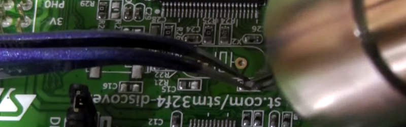
That leaves just one other question; the original discovery board had an in-line resistor on one of the crystal traces which he replaces with a zero ohm jumper. Is it common to include a resistor and what is the purpose for it?


A resistor is sometimes used to make the rise-time of the clock slower to reduce noise.
I haven’t used any of the STM32 series. Most MCU’s have 4 oscillator modes.
1) RC network – very low frequencies (kHz)
2) Ceramic resonators – below about 4 MHz
3) Low power crystal mode – up to about 8 MHz
4) High power crystal mode – anything above that.
5*) You can always direct drive the clock input with an external crystal oscillator.
There is confusion in the video between what is a crystal and what is an oscillator.
A crystal has 2 pins / connections and cannot oscillate without other circuitry (inside the MCU) and is NOT an oscillator.
A crystal oscillator (sometimes called an active crystal) has 4 connections (of which three are used) and has the extra circuitry inbuilt so it can oscillate without additional circuitry and is therefore and oscillator.
Getting back to the MCU clock modes.
High power crystal mode swings the crystal from rail to rail (full Vcc) and for this reason it will work with higher frequency crystals even when PCB capacitance shunts (shorts out) some of the signal. It does however consume more power to do this which isn’t an issue except for really low power applications like running on a button cell battery.
Low power crystal mode usually swings the crystal from 1 third Vcc to 2 thirds Vcc as it can easily get away with this because the PCB doesn’t shunt that much of the signal at the frequencies used for low power mode.
The mode is set by software by changing a register with code.
The 8 MHz crystal was probably already working in high power mode. I would have just changed the crystal and tested it. If it didn’t work then I would re-program the mode to make sure it was in high power mode. Only if that failed (which I haven’t seen before) I would then think about changing the caps.
But I suppose changing the caps might save you the trouble of worrying about the mode that is programmed.
One other thing. Some MCU’s will clock much faster than the internal crystal oscillator circuitry can run at.
For example, much of the atmega series wont oscillate much higher than 20MHz but if you us an external crystal oscillator (active crystal) they will happily run over 30 MHz.
I’ve used the ltc 1799 successfully up to 20 MHz, although I would recommend replacing the pot with a fixed resistor once you have the desired clock. Anytime I have messed around over the 30 MHz range, the device usually has clock dividers or multiple clocks that seem to make it ignore changes to a higher frequency or a crystal @ 80MHz will yield only incrementally faster speeds. I apologize if I am way off, I am mainly referring to my experiences with over and underclocking mcus and am no ee.
Your chart is pretty good for what I have seen in my experience.
Thanks for the helpful links, folks :)
STM32 parts are rated for 26 MHz max crystal speed
“The 8 MHz crystal was probably already working in high power mode.”
nope, on STM32F4Discovery by default the clock for the STM32F407 is coming from the clock on the ST-Link processor. If you take out your STM32F4Discovery and compare the jumpers to the schematic you will see that the OSC_IN signal is connected to the MCO output of the ST-Link processor.
Everything you need to know about crystal and component selection for the STM32 is in this document: http://www.st.com/web/en/resource/technical/document/application_note/CD00221665.pdf . It goes into the background on how the oscillator works and covers the selection of series resistor, capacitors, crystal ESR, layout, etc. In my experience, the STM32 oscillator is a little more finicky than some other microcontroller brands, so it’s definitely worth a read.
The ST paper is a good discussion of oscillator design. Go read it.
Regarding the series resistor: Generally, the only time you really need to to worry about overdriving the crystal is when it is a “tuning fork” style (32kHz watch crystal), or when unintentionally jumping to a crystal overtone mode. There may also be the occasional customer who has had issues with EMI radiation from the oscillator and wishes to reduce emissions from this source.
Usually, the opposite is true – the customer needs to be sure the oscillator always works, even with an aging crystal under hostile conditions (automotive customers). The series resistor is used for testing/qualification. Given the series resistance of the crystal, the robust oscillator will still start and run with an external series resistance on the order of 5 to 10 times the crystal resistance (this would be the “safety factor” mentioned in the paper.) The extra gain required to ensure operation with the resistor present simulates (somewhat excessively) the losses that develop over time. Final production versions of this circuit would not have this resistor.
For those instances where you really need to know much power the crystal is being driven with, a series resistor is about the best way to measure crystal current, but you still need low capacitance probes (<10pF) to avoid loading the circuit (also discussed in the paper.)
In most cases, removing the resistor causes no harm.
I learned something new today.
Upon some additional googling I found this adafruit blog:
https://blog.adafruit.com/2012/01/24/choosing-the-right-crystal-and-caps-for-your-design/
Using the formula CL = (C1 * C2) / (C1 + C2) + Cstray, with CL = 18pf and Cstray = 6pf, C1 & C2 should be 24pf, not 30.
Instead of hot air gun, I would just get it out with a regular iron. Put a big blob of solder on the board, and quickly move it back and forth between the two crystal pins. With the hot air gun, it’s very easy to make the board too hot, like he’s doing in the video (the brown discoloring is a bad sign).
The little capacitors can be removed similarly.. put the iron next to the cap, and add plenty of solder to melt both sides at the same time.
That probably works because you’re mixing the RoHS solder with a lower melting point solder. You could alternately just melt in some low melting point solder on the pads, and then use the heat gun at a lower temperature. Lots of ways to skin a cat.
Yes. In this case with the through hole crystal a good solder sucker would probably work too, since it’s not attached to a ground plane. Or mix in some leaded solder, suck it out, and repeat to lower the melting point first.
hot tweezers are the the way to go with SMT removal
if you don’t have hot tweezers you have about 50% chance of trashing the board
with hot tweezers this is so easy it doesn’t qualify as a “hack” any more
380°C THAT IS WAY TOO HOT!!!
Not for ROHS solder. Then its exactly right.
If the PCB starts to turn brown, that’s a sign that it’s too hot.
no, that’s a sign you’re not doing it right. with a very hot iron, you’re done so fast the board doesn’t have a chance to burn
TI, Micrel, LT, etc all max 260°C, read the datasheets
lest we forget, the entire point of this exercise is to save a part or two on a system with an Ethernet port that requires a 25 MHz clock. Instead of using the HSE clock for this, you can just use a 25 MHz crystal like the one on the Waveshare DP83748 module.
Nice job on the rework, but wasn’t really necessary. The 25MHz could have been generated from MCO2, using the part of the clock tree designed to generate I2S clock.