A lot of microcontroller projects out there need some sense of wall-clock time. Whether you’re making (yet another) crazy clock, logging data, or just counting down the time left for your tea to steep, having access to human time is key.
The simplest solution is to grab a real-time-clock (RTC) IC or module. And there’s good reason to do so, because keeping accurate time over long periods is very hard. One second per day is 1/86,400 or around eleven and a half parts per million (ppm), and it’s tricky to beat twenty ppm without serious engineering.
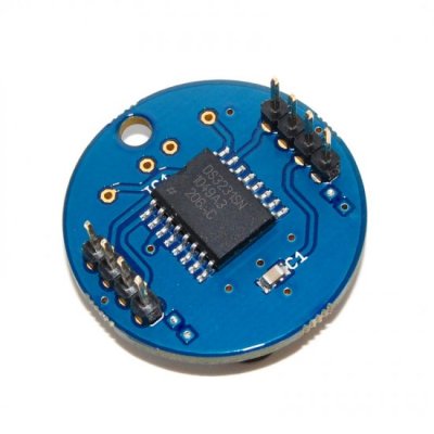
Good RTC ICs like Maxim’s DS3231, used in the Chronodot, can do that. They use temperature correction logic and a crystal oscillator to get as accurate as five parts per million, or under half a second per day. They even have internal calendar functions, taking care of leap years and the day of the week and so on. The downside is the cost: temperature-compensated RTCs cost around $10 in single quantity, which can break the budget for some simple hacks or installations where multiple modules are needed. But there is a very suitable alternative.
What we’re looking for is a middle way: a wall-time solution for a microcontroller project that won’t break the bank (free would be ideal) but that performs pretty well over long periods of time under mellow environmental conditions. The kind of thing you’d use for a clock in your office. We’ll first look at the “obvious” contender, a plain-crystal oscillator solution, and then move on to something experimental and touchy, but free and essentially perfectly accurate over the long term: using power-line frequency as a standard.
Crystal Castles
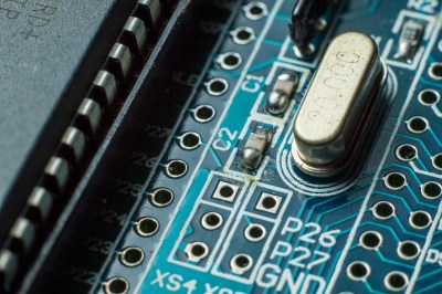
If you don’t need very high accuracy, perhaps you can gain or lose a minute or two per month and it’s no big deal, then there are a ton of cheap crystal oscillator solutions that’ll work for you. In fact, you may even be clocking your microcontroller with one right now: that’s certainly the case with Arduino which have a normal-looking crystal on board and are probably good for something like around 10-50 ppm.
The problem with crystal oscillators is temperature. While any given crystal may keep a stable frequency to within a couple parts per million at a single temperature, this frequency changes when the temperature changes. Indeed, if you want very high stability you can hold the temperature of the crystal constant by putting it in a small insulated “oven” and you’re set.
This temperature dependence is why the manufacturers’ specifications are given as ppm over a given temperature range. And the same goes for the simple RTC units that use the ubiquitous 32.768 kHz crystal. But even if the frequency is reasonably stable, say you’re keeping the circuit indoors in a climate-controlled building, the crystal oscillator won’t necessarily be accurate. That is, the frequency of your 8.000 MHz crystal might be, at some temperature, a very stable 8.001 MHz. If you want serious accuracy, you’ll want to calibrate this.
Note that this is also true of the internal RC oscillators that are found in many microcontrollers, although the situation is more complicated there because the frequency depends on operating voltage as well as temperature. If you’re able to hold both temperature and voltage constant, you can get decent performance from the RC oscillators as well.
Calibration isn’t conceptually hard, it’s just a pain in the astable vibrator. If you have patience and a good time source, you can get very good results for indoor use by running the crystal clock for 24 hours or longer and figuring out how many seconds fast or slow your microcontroller runs and adjusting accordingly in code: adding or subtracting leap-milliseconds periodically as necessary. If you repeat this calibration over a few days, possibly picking a hot day and a cold day, you can get decent year-round accuracy for almost no added cost except for a bit of firmware overhead.
Power-line Time
But all of this calibration and temperature-control is a drag. And it’s worse still if you have to calibrate multiple devices. It’s much better to let someone else take care of accurate timekeeping for you. Someone who could broadcast a timing signal to all of your devices simultaneously. Someone like your local power utility.
In many parts of the world, the AC power runs at a very well-regulated 50 or 60 Hz. While the timing can vary a lot over the day, depending on things like what kind of generators are providing you with power and how much aggregate demand there is in the system, power utilities try to maintain a ridiculously accurate long-run average frequency. So much so that powerline driven clocks can rival the best TCXOs for accuracy over the long run.
 For a reliable wall-time solution, using a transformer to reduce the wall voltage down to something that the microcontroller can handle is the way to go. If you’re already running your project off of a wall-wart, you might even be able to open up the case and tap into the low-voltage AC directly as it comes off the transformer. You might additionally want to run the resulting 50 Hz or 60 Hz sinewave through a lowpass filter to smooth out power-line noise so that you get nice clean low-high logic transitions. Maybe even square up the sine waves with a Schmitt trigger.
But what if we went even more minimal? We’ve often noticed that the 50Hz (a European standard) hum of the power line works its way into any high-impedance input that gets left unconnected, so why not treat the noise as the signal and try to run the microcontroller real-time clock off of radiated power line
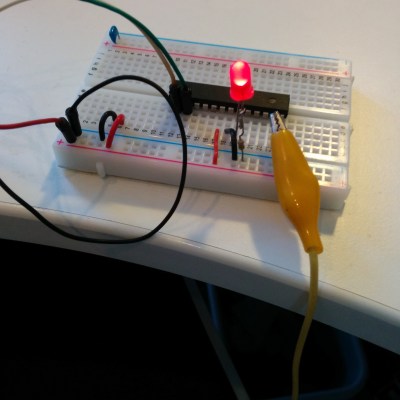
We hooked up an alligator clip to an input pin on an AVR Mega168, and used the chip’s normal input conditioning circuitry in place of any external parts. When the voltage on the pin is high, the input reads a one. Done. Microcontroller logic inputs have high enough input impedance that the voltage imposed on the pin swings back and forth with the received power line noise signal.
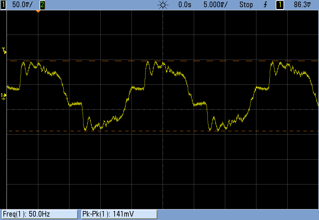 The logic transitions were fairly glitchy, and you can see why from looking at the output of our “antenna” on the scope. We went for quick and dirty debouncing in code; we just waited one microsecond after the first rising transition to wait out the effects of higher-frequency noise.
With that sorted out, we got an LED blinking at what looked like one second intervals. But how accurate is the powerline signal anyway, and will it be reliable enough to use as a clock?
To find out, we had the microcontroller send a byte to our laptop once per “second” over a USB/serial connection. On the laptop side, a Python routine received the incoming byte and logged the system time when it arrived. Now, the laptop’s internal clock isn’t all that accurate either, so the laptop was synced to an NTP server.
It might be better to use a GPS’s pulse-per-second output as the reference timing source, but we have bad GPS reception in the office. It should all be good enough. But bear in mind that the difference between the power-line clock signal and the laptop’s time will necessarily be the sum of both parts’ errors.
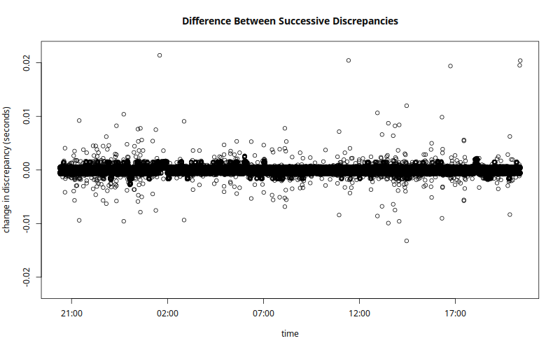 You’d expect the reception of the power-line noise “signal” to be the Achilles heel of this method. After all, the antenna consisted of a random-length alligator clip just draped on our desk, but it seemed to work very well. At 50Hz, one cycle is twenty milliseconds, so a missed cycle would appear as a sudden change in the computer-microcontroller time discrepancy of twenty milliseconds.
We saw only five jumps of that size during the 24-hour period that we left the experiment running. One hundred milliseconds lost per day is 1.16 ppm, so even this completely ghetto antenna is not the limiting factor here.
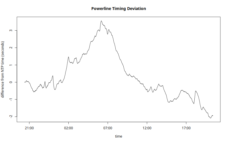 What we did see was a lot of gradual shifting back and forth around our initial starting syncronization. (Note that there’s no significance to the “zero” in time sync error; it’s just the initial difference between our laptop’s clock and the microcontroller’s.)
Power-line time generally runs a few seconds slow during the day, is worst in the evening when everyone gets home from work, but catches up at night when the generators are more lightly loaded. In this sample, the clock went as fast as 3.6 seconds ahead in the morning and as slow as 2 seconds behind at dinner time. As long as the power company ends up with an average of 4,320,000 cycles per day, which they aim to do, the clock will stay accurate year-round.
The slow variation in clock speed over time means that if you need very precise timing from minute to minute, the powerline method may not work for you.
On the other hand, if you simply need a microcontroller to accurately count up the right number of seconds in a day, using received power-line noise seems to be nearly ideal. Even though the clock ran fast or slow most of the time, it should average out well enough to beat a good TCXO for long-run drift if the utilities are doing their job.
So there you have it: an accurate clock powered by the electric utility company, made out of a crocodile clip hanging over the side of the desk and a few lines of code.
The main downside of using radiated power line noise instead of a dedicated RTC chip are the lack of battery backup that most RTCs have these days. And of course it breaks down when the wall power goes out. For a fully featured calendar application, you have to take care of leap-years and stuff like that yourself, but there’s standard libraries for that (AVR version).
Questions?
Any of you out there use the power-line frequency for timekeeping? How’s it working for you? Any tips or tricks? Does it still work in the US? Can you think of a better antenna design or perhaps some input conditioning circuitry that would improve on our results? Post up in the comments.


I’ve had good luck with the 60Hz coming from the wall, with a call to a nist time server once a week.
As Dad use to say, “Close enough for government work”.
“It’s much better to let someone else take care of accurate timekeeping for you. Someone who could broadcast a timing signal to all of your devices simultaneously.”
Maybe some one like the US government? Maybe on frequencies like 2.5Mhz, 5Mhz, 10Mhz, 15Mhz, and 20Mhz…
Or course if you can’t get GPS reception odds of getting shortwave radio reception are probably pretty low…
If you’ve got any references on receiving this and equivalents, I’d very much like to see it. I looked into receiving unmodulated 60KHz time signals here in the UK, and it was a pain – all the existing receiver circuits demodulate as well, which is useless if you want to use it to discipline a TCXO.
There’s ready off-the-shelf GPS disciplined oscillators.
Don’t forget WWVB at 60kHz!
And DCF77 on the European side of the world. At 77.5 kHz, it’s around 1.3 times better than WWVB!
Unfortunately, it’s also completely interfered-with by my favorite computer monitor.
There is also a once-per-day time signal on the 700 THz band. Too bad that it also has poor reception indoors.
700THz, huh? Is that transmitted by a satellite? Am thinkink wherever this signal comes from, it’s not only difficult to receive indoors, but also difficult to receive in the dead-of-winter near the poles.
didn’t got the joke, don’t you?
It appears you didn’t get hís joke. The 700THz transmitter doesn’t have a line of sight with the poles during winter ;)
I hear (see?) it gets bad on cloudy days too.
It’s got this wierd seasonal drift to the clock though. Needs temperature-correction.
And doesn’t account for daylight-savings time.
do you mean the 11,574 µHz signal ?
Yes, but it comes on a carrier frequency of 700 THz. And it’s AM, does anyone still use that? The pure 11,574 µHz signal comes on Higgs bosons, but there’s a lot of noise, mainly at 4.134 nHz.
Interesting approach, especially the antenna. I wonder how practical it would be to make a powerline-disciplined-TCXO (with very long averaging period) based on this?
Well, the source the author quotes states a daily accuracy of ~100ppm — so that’s worse than your standard oscillator, and definitely not usable for short-term corrections. You’d need a much better oscillator to run while you take the “longer-than-a-day-average”. Basically, this boils down to getting a very good oscillator.
…the TCXO is the “much better oscillator” you refer to. The point of disciplining it with this would be to control for long-term variations in frequency accuracy.
Now the real exercise for the reader would be to use that in a PLL to keep the microprocessor’s clock calibrated (kind of like NTP does it). This would address the battery backup thing, and — with a suitably chosen large PLL time span – might even take care of the daily fluctuations.
The design of that algo might turn out “interesting”.
For the really ambitious, and if there is an on-chip temperature probe available, the next step would be to keep a drift/temperature table updated in a feedback loop…
In principle it’s a fairly straightforward PID controller. Accumulate a count of the difference between divided-line-frequency-cycles and divided-MCU-clock-cycles, and use a (very, very small) proportion of that to tweak the trim frequency up or down.
It’s a fairly simple algorithm. Program MCU to produce an interrupt per second, update long term average of line frequency cycles, and add that average to a time variable.
At least for Germany you can look at
http://www.netzfrequenz.info/
The entire european power grid is unified, so this reading is correct for a whole lot of countries, including some in north Africa.
I like the meter on http://www.mainsfrequency.com/ , it’s especially fun to look at at 00:00 UTC, when the frequency drop is most “extreme” (~0,15Hz).
These are both great resources.
Too bad they don’t keep track of the long-term drift / integrated error, which is what matters for keeping your clock in line.
That’s not entirely true. The frequency changes slightly between different parts of the network, and some countries such as Swizerland are employing phase-shift transformers in order to shield their grids from power loops coming in from the German grid, to stop their overproduction of wind power from spilling over and tripping all the fuses.
Here’s an example:
https://www.swissgrid.ch/swissgrid/en/home/reliability/wam.html
The differences in grid frequency between different locations actually represent the direction of power flows, because the part of the grid with a higher frequency is slowly advancing in phase relative to the part with a lower frequency. The one ahead in phase is pulling the slower one along.
The generators in the slower area will automatically speed up because of the inflow of power, but if the grid isn’t managed carefully, the dispepancies between areas can grow too large and the phases slip to oppose each other, causing a massive power surge and an automatic shutdown.
This is essentially what happened in 2006 when there was a large storm in northern Germany and one of the high voltage lines to the south was out of operation because of a ship passing underneath. A surge of power from wind farms in the north tried to take the long way around through the French grid which was already loaded, which desychronized the grid and caused a cascade failure that spread all the way through to Portugal and Italy, making a round through the entire continental grid.
I’d expect serial buffering to introduce some jitter into those measurements, especially where USB-to-serial is used.
Yeah. Good call.
If you zoom in on the plot of times between reports, you see that there’s essentially two modes about equally: http://imgur.com/OlAvcKO
I’m guessing that’s USB jitter.
works pretty well.
http://hackaday.com/2010/04/30/using-ac-frequency-as-a-clock-signal/
http://hackaday.com/2012/07/24/hows-the-60hz-coming-from-your-wall/
http://hackaday.com/2010/04/07/logic-clock-without-an-on-board-oscillator/
Clever idea. I’ve seen contactless power line detectors that use the same antenna technique (usually amplified), so the concept is sound.
I’ve looked at line frequency timing for the design of an electrical timer, but I’m concerned about frequency regulation becoming less reliable as more power comes from unpredictable sources like wind and solar.
http://m.pv-magazine.com/news/details/beitrag/as-it-happened–germanys-grid-grapples-with-solar-eclipse_100018709/
If your product already has Wi-Fi, you can use the NTP protocol to obtain accurate wall clock time. Saves you from having to set it, too.
simpler than ntp: on an arduino with the ESP wifi, I wrote a small bit of code that will grab the http header from any website (ebay, maybe? google?) and get the UTC time from it. no messing with ntp or any protocol; simply get ascii header from a wget or something (curl, really):
% curl -sGI http://www.ebay.com | grep Date
Date: Wed, 01 Jul 2015 15:41:48 GMT
do the same on a controller, parse out the date and you’re done. really really easy and everyone lets port 80 OUT of their network (I was at a big networking company who filtered ntp, so ntp to a public server would never work inside their stupid firewall). port 80, sure, it always goes out and comes back in ;)
A simple NTP client doesn’t take much effort. You send a single UDP packet, and you get a single UDP packet back with a 64 bit timestamp. In the UDP packet you send, you only need to set the first byte, and leave the rest as zeroes. It’s simpler than TCP+HTTP, and has less surprises.
but again, you may not be able to get ntp OUT of your network. there may be local time servers but if you expected to get to a public one, you may be behind firewalls that block it. that’s the beauty of the web get method. port 80 is always allowed out and grabbing time is simple ascii, so its easy to develop and test and implement. and its definitely good enough to set clocks by.
ntp is more ‘pure’ but if you can’t get to an ntp server (easily), then its a complete non-starter.
at any rate, its good to have choices. on my clock systems, I try to grab time from many places (gps, local rtc chip, ntp, web) and so I can usually find -one- that works ;)
(on my time system, I have a master system (rasp pi) and it beacons out time over xbee serial; so any of my other ‘boxes’ that can listen on xbee can get time that way; very lightweight and distributed for low power, non tcp-ip but still ‘connected’ systems.)
oh, forgot one of my more fancy time sources (or clock sources, at least). I did build a diy rubidium 10mhz (with 1pps out) osc and for grins and giggles I plan to have that also feed into the time keeping system. again, many sources is a good thing and you can discipline local clocks with multiple long-term stable clocks.
Doesn’t rubidium osc modules draw quite a lot of power, in the order of ~$10 per year?
Using the power line frequency as a time reference has traditionally worked very well, but there has been talk of reducing the accuracy of the frequency in the US.
My thoughts exactly. Some claim that it’s not as important anymore or some nonsense.
The reason is that greater differences in frequency and phase allow for power to flow between different sections of the grid more easily. Frequency on the AC grid is very much like voltage in a DC grid – current tends to flow from higher to lower.
By allowing greater differences between different parts of the network, they’re allowing power stations further away to contribute to local variations in demand, which makes it easier to manage things like varying output of renewable energy.
Just out of curiosity, how would that work? If there’s less accuracy among the individual parts of the power network, wouldn’t precision suffer along with a greater risk of various parts of the power grid being slightly out of phase with one another?
I’ve been told by an expert in the field that most sources self synchronize with the grid they supply. It takes more energy to generate power out-of-phase, so the generators tend to fall into step automatically.
The problem isn’t that one part of the grid is out of phase with the rest, but that the frequency of the entire grid drifts.
Different parts of the network being slightly out of tune is a normal condition of an AC grid. When two parts of a network are perfectly in tune in frequency and phase, no power is flowing between them. When one starts to lag behind, the power starts to flow from the faster to the slower until they have synchronized in speed again. The difference in phase angle therefore represents the amount of power flow, and the difference in frequency the rate at which the flow is changing.
I wonder what other signals are floating out there you could use as well? I know of the standard time keeping signals (WWV, CHU, etc.) but for example, how accurately are the carriers of your local radio stations maintained? I also seem to recall that, before the move to digital, the blanking intervals on TV signals were accurate enough for this sort of thing.
I recently disinterred a 40 year old hack and, to my pleasant surprise it still worked. It was an LED wallclock based on 50Hz mains. It was the first most people had seen, and some hated it because they could see the seconds of their life ticking away. I’ve documented what I found and how I turned it into a Vetinary clock at:
https://entertaininghacks.wordpress.com/2015/02/21/a-40-year-old-hack-disinterred/
https://entertaininghacks.wordpress.com/2015/02/23/vetinari-digital-clock/
https://entertaininghacks.wordpress.com/2015/02/21/vintage-hacking-or-the-past-is-a-foreign-country-they-do-things-differently-there/
I’m not sure how I feel about a floating antenna connected directly to an MCU pin. Sure, it seems to work on your workbench, and quite well at that. But I don’t really trust it. With a sufficiently strong/near RF source at any fractional wavelength of the chosen antenna, wouldn’t it receive that far more efficiently than 50/60hz, and the timebase go to hell? I’d bet you a good beer it wouldn’t work at my workplace, when they fire up those TIG welders, regardless of antenna length. ;)
I hate criticizing something without providing an alternative, which I can’t always do. But in this case I can. Use a trimmed and temperature-corrected crystal oscillator as the clock source for your MCU. Most are predictably expensive. But commodity GPS systems use such oscillators, and if you can use one of the common frequencies used in such systems, thanks to mass manufacturing you can get those much cheaper. For example, Newark lists:
7Q-16.367667MCN-T, 16.368Mhz, $0.525
7Q-20.000MCN-T, 20Mhz, $1.21
Both are single quantity prices, stocked, and with accuracy from 0.5ppm-2.0ppm. The latter costs more, but is friendlier due to being a nice integer Mhz. Looks like 24 and 26Mhz are also common integers.
Actual frequency doesn’t really matter too much if you use a timer interrupt along with something like a DDS type of accumulator to increment the software RTC. With that scheme, you can even trim the accuracy too.
Both good options if your micro doesn’t mind running that fast. Give me 16.384 instead and you’re talking.
Totally good idea to look for a consumer product that needs the part you want, though.
Been bouncing this one ’round the ol’ noggin’ for a couple years now… initial research found someone online used a (large) tuned coil to pick it up, but an aligator-clip sure beats that for simplicity!
Wonder how reliable it is if the device moves around the room… Does it remain stable when a person walks by (or picks it up)? How ’bout if it nears a large metal object…?
And I gotta know what kind of oscilloscope probe could be connected (or how to connect one) to this “antenna” without acting as an antenna, itself (or at the very-least a comparatively low-impedance load?), dramatically changing the input-signal…?
This all sounds skeptical, but really, it’s filled with optimism!
What you’re looking for is an active (sometimes called FET) probe. This is the main reason modern scopes have additional signals on the probe connector besides the standard BNC.
Atmel has an application note about making a simple zero-crossing detector with nothing more than two resistors (PDF warning):
http://www.atmel.com/images/doc2508.pdf
This works by using the micro’s internal clamping diodes to keep the voltage between VCC+0.5V and GND-0.5V. External high-value resistors limit the current to keep the diodes from failing. Pretty cool, actually.
Obviously this isn’t nearly as safe, but it’s more reliable than detecting through noise. Make sure the resistors are rated for the proper voltage! It’d probably be a good idea to use a transformer to drop the voltage and isolate the micro a bit.
You can even reuse the same code, or Atmel has provided code as well.
You can make it safer with an optocoupler. Use a suitable capacitor + resistor to limit the current, and put a diode reverse parallel to the LED to prevent high reverse voltages.
That’s so ghetto coming from a chip company! But at least it shows they have confidence in their clamping diodes…
Note if you’re doing this at home: the chip (and possibly it’s power supply) is potentially at line voltage. Best put it in a box, and don’t probe at it with your formerly-expensive oscilloscope.
Here in the US they used to count cycles and speed up or slow down the line frequency at the end of the day to compensate for however far off it was. So.. used as a clock you never got very far off before it was corrected. But.. I seem to remember reading a few years back that they were going to stop doing this.
I collect data from ERCOT (Texas grid) on power generation and that data includes line frequency and the current integrated time error. I created a plot of the time error for last year:
http://home.earthlink.net/~schultdw/power/2014_time_error.png
The x axis is just sample number and the data runs from 1 Jan. to 31 Dec.
Awesome data. If I read that right, the powerline clock stayed within 5 seconds over the whole year? Not bad, long-run.
It stayed in that range during 2014 but digging into the rest of the data I have shows that might have not been the norm.
In 2013 the range was from -20 to -30 seconds but 2015 is very different. While it started out much like 2014, in the last couple of months it made a pretty steady march to +8 seconds.
DS3231 is less than $2.50 on a nice PCB with a battery and EEPROM:
http://www.dx.com/p/ds3231-high-precision-real-time-clock-module-blue-3-3-5-5v-222910
I don’t like it when an article is based on a false premise. $10 indeed!
That product might be based on a false (or counterfeit) DS3231. I’m pretty sure Maxim is the only company that makes these, and they don’t sell them that cheaply.
+1
but: Elliot was still of by 25% (an error comparably small when one reads the article):
http://www2.mouser.com/ProductDetail/Maxim-Integrated/DS3231S-TR/?qs=sGAEpiMZZMtqHvhDiVRlwy6pKJhhSRD1
7.25$ single quantity.
…and some of that may be EU markup. I notice that Mouser’s prices are about the same here in Euros as they are in the states in dollars. That gets me at least another 10-15% at today’s exchange rates!
But point taken.
Ah if you’re not fixated on maxim: NXP has the pca2129 for ~5.30USD; it’s an RTC integrating the quartz.
It’s amazing how a little market research can make your article look a little weak, though it’s been so much solid work!
http://www2.mouser.com/ProductDetail/NXP/PCA2129T-Q900-251/?qs=%2fha2pyFaduh6wyuyNf36cpPBUOizhLrTVfebO1JOxr4%3d
I was wondering about that. Maxim’s quite expensive, not something to use in a project or even as a representative price if it can be avoided. Although sometimes they’re first to market with a particular functionality, or have superior specs that make it worth it.
They might have been first to market in this case. Best I can tell, the DS3231 has been around since early 2005. The Chronodot since 2009. The PCA2129 wasn’t released until late 2012.
But considering the Arduino generation favors throwing money at problems over soldering, coding, and reading datasheets, perhaps the DS3231/Chronodot is STILL a better representative price. At least until someone provides a ready-to-use PCA2129 module and library.
And that’s a great find for when you _do_ need an RTC. I’ll keep that in my memory banks.
I fail to see how a ridiculously long average leads give you a “ridiculously accurate long-run average frequency” — 6.4ppm is not really a rival to a good TCXO if you need your time to be right during that integration time; it’s really no use if your clock is right at 8:00am but off by a few seconds by afternoon, swinging back during the night. So, you’d need an oscillator that you can ever so slightly discipline with the powerline frequency. Directly following powerline isn’t an option. Hence, you need an oscillator with very little drift itself. You hence need an oscillator in the same order of accuracy that you’re trying to achieve.
Note that this is very much different from e.g. the GPS disciplined clock approach because your refence clock needs such a huge integration time to get exact. To be honest, powerline is a terrible approach in the year 2015. People in urban areas might just want to generate 2G frequencies from their oscillator and pull that one till using band edge filter loop to lock in on a specific base-station produced frequency. That would definitely be better than the 15$ TCXO that would beat the hell out of powerline accuracy.
In before “link or unsupported claim”: 2.5ppm (worst case I’d say 4ppm) temperature compensated oscillator:
http://www2.mouser.com/ProductDetail/ABRACON/ASTX-H11-10000MHZ-T/?qs=sGAEpiMZZMt8oz%2fHeiymABpGe7%252bQFKd8%2fFcbwFpd3mU%3d
4.47USD single piece quantity.
Also: you forgot to mention that taking of your f_calibration << f_oscillator signal off the air might be a bad idea simply due to noise, and the fact that switch-mode power supplies do in fact do funny things to the (what you though was 50Hz) spectrum you're seeing. So plugged into a complex network (the typical home power supply situation), this might perform much worse.
But then again: 5$ for a RTC including the temperature-compensated quartz? Why not:
http://www2.mouser.com/ProductDetail/NXP/PCA2129T-Q900-251/?qs=%2fha2pyFaduh6wyuyNf36cpPBUOizhLrTVfebO1JOxr4%3d
PERFECT AND WELL SAID !!!!
PCA2129 is just TOO GOOD an opportunity to pass down !!!!
BLOWS ALL OTHER RTC’s OUT OF THE WATER !!!
How much is a 3PPM TCXO or OCXO ? ==—>>> i can assure you that the price of such an accurate crystal AND buying, say, a DS1307/DS3132 is STILL Cheaper for the all in one package PCA2129.
SHAME until this date there isnt a module/library for it… Love SMD stuff ! lol
I did a project with WWVB, but reception of that signal for me in the summer isn’t terribly great.
If it were me and if the project had a regular AC power cord coming into the enclosure, I’d wrap your antenna a few turns around the hot wire and use some clamping diodes (or an op-amp) to make it more predictable.
Of course, the old saying is that the only truly accurate clock is the one that’s stopped. It’s perfectly accurate twice per day.