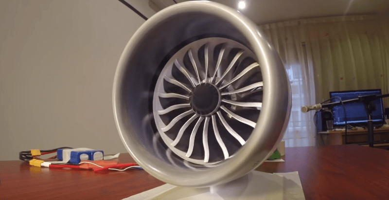
[Harcoreta] has created a 3D printed model of the GE GEnx-1B Turbofan. This is the engine that powers Boeing’s 787 dreamliner. What sets this model apart is that it has a complete working reverse thrust system. A real jet engine would be asking a bit much of 3D printed ABS plastic. This model is more of an Electric Ducted Fan (EDF). An NTM 1400kv 35mm brushless motor hides in the core, cooled by a small impeller.
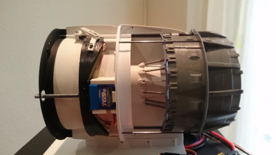 What sets this apart from other jet models is the working reverse thrust system. [Harcoreta] painstakingly modeled the cascade reverse thrust setup on the 787/GEnx-1B combo. He then engineered a way to make it actually work using radio controlled plane components. Two servos drive threaded rods. The rods move the rear engine cowling, exposing the reverse thrust ducts. The servos also drive a complex series of linkages. These linkages actuate cascade vanes which close off the fan exhaust. The air driven by the fan has nowhere to go but out the reverse thrust ducts. [Harcoreta’s] videos do a much better job of explaining how all the parts work together.
The model was printed on an Reprap Prusa I3 at 0.1mm layer height. [Harcoreta] smoothed his prints using acrylic thinner, similar to the acetone vapor method. Unfortunately, [Harcoreta] has only released a few of the design files on rcgroups, but we’re hoping he will drop the whole model. We can’t wait to see a model dreamliner landing just like the big boys!


Not a chance he’s going to post anything but that fan model:
“I have a lot of petitions for the engine files. Sorry but I can’t do that now It’s very difficult to do a successful build, I’d have to do a detailed tutorial and it really have a lot of parts and tweaks. But I’m looking now for upload only the rotor fan. It’ll be in bigger scale for easy print, and It could be a curious decoration piece ”
Don’t know why the writeup here said otherwise
Unless you want a decorative fan model for your desk, don’t waste your time, like I did, on that forum thread
AKA “I downloaded a turbofan model and 3d printed it so people think i made it”.
These guys should try to make a square hole like i did 2 days ago for a front aluminum panel PSU with just a file and a hand drill and take like 2 hours of work to do it.
Now “He then engineered a way to make it actually work using radio controlled plane components”.
WTF?
He didn’t engineered nothing, he just grabbed some servos and a 40.something mhz receiver to make it work.
Today people think 3d printing something makes them big male.
Ask tubalcain or keith fenner what is how to really make things.
This is just my opinion, right or wrong, for me Tubalcain and Keith Fenner are the bosses.
Ps: i dont believe the author did the jet engine model at all.
I don’t say your wrong (or right for that matter), but in the scond video you can see that he had to (at-least) take the feedback potentiometers out of the Servos and mount them to seperate linkages.
It is really well made, its true, but sorry for being anti 3d print guy.
First off – you’re right about Keith Fenner, Tubalcain, and the rest of the YouTube Machining crew. Don’t forget about Clickspring in there – he’s awesome as well.
Secondly – you’re dead wrong about [Harcoreta] and that jet. Anyone who looks at the 3D renders on RC groups, and the internals video on youtube can see that. You just can’t eyeball a brushless motor, servos, and those vane linkages.
If any of those parts are available to download elsewhere, that would be a surprise to me. I’ve looked around. You can’t just print beautiful parts either, so I doubt you’ve ever used a 3D printer if you think that just happens.
I wonder where he works. You sometimes find commercial models floating round academic institutions or similar etc if they do some work with industry.
I wouldn’t be entirely surprised if it’s a rework of a commercial model that’s been simplified and scaled down. Maybe he won’t release the files because he’s afraid of GE showing up with their lawyers!
I actually have done just that a few times – used commercial models I would not be able to distribute to make some project or other – or simply 3D renderings.
people don’t understand how design and 3d printing works. Very often, you can’t design things to just pop out of the printer and function perfectly. a lot of post processing has to occur, from cleaning up and cutting material away, to threading holes, to gluing shit together. It is a nightmare, and the thought that something like this is just a button press away with a 3d printer is a farce. I don’t follow this thread or know this guy, but he’s good with his hands and he made magic happen after the files printed out. There is nothing wrong with him explaining that his engine can’t be reproduced just by 3d printing all the files – he would be leading people on a wild goose chase and waste their printer material without fully documenting everything he did after printing.
Wow. I’m blown away!
Seriously though, that’s amazing.
Honestly, I don’t care if he downloaded the models – that’s still amazing
+1
This was in the hackaday links not een a month ago:
http://hackaday.com/2015/08/30/hackaday-links-august-30-2015/
I knew I had run across this a while ago, but I didn’t remember it was from here also. Good catch.
Seriously it has a 1400 kilo-volts engine inside?
kv rating is RPM per Volt.
Unloaded RPM per volt, specifically.
It’s the speed at which the back-EMF from the spinning rotor (generator action) equals the input voltage. The motor won’t actually quite reach it because there’s some friction and drag by air resistance and the bearings.
More correctly, kRPM per volt.
Hmmm … nice project, no question. Then again – the guy with the file making a square hole in sheet metal has a point too: with everything modular & lots of free files on the web, I fail to see what’s so great about putting stuff together. When I look at projects like this, I want to see if people understand and make smart use of the basics – be it the use of a lathe, file or by pretzeling a resistor and a FET into a current limiter.
Very often, the overall WOW is quickly reduced to a MEH, when I see that people can’t use a file or any other hand tool and every component is wearing the hallmarks of impatient Dremel work. Also, a poor understanding of the mechanical properties / stress is (literally) covered up with epoxi and hotglue – typically, after the first test run… To quote the ship builder William Fife: “If it looks right, it IS right” – meaning the aesthetics and the intelligence in the details can not be separated from the overall concept.
In the project above, I see some severe engineering flaws in the printed parts. A better approach would have been to first understand the function of the respective element, then look at the forces involved and make the necessary modifications (reinforced bushings, stiffening out some cross sections etc.) BEFORE printing the parts…
I am afraid you dont know what you are talking about at all.. Lol. Some posters spell out the level of skill involved in their comments above. Read them.
Um … as product developer, I use 3D modeling and CNC milling since I graduated in the 90s (Alias, 3D Max, DELCAM surfacing tools) but I am also a fully trained model-maker. Currently, my team uses 2 CNC mills and 2 3D printers in-house while we have sub-contractors do our laser-sintering parts (stainless and PA). All our designs are validated through RP processes of some kind before I ok them and they go into the master drawings. Whilst I don’t have the time any more to do a lot hands-on modeling myself (mostly using Rhino), I get paid for spotting design flaws before the mold-makers cut in steel.
I also teach in the context of design development. My advice to people before showing (off) their work is this: Did you make significant progress from a PRODUCT or a PROCESS perspective? If yes, ok – if no: invest more work. The project above is ok-but-not-phantastic in both dimensions.
About the level of skill praised by “somebody on the internet”: I’m not doing the homework of other people here. If you don’t know what the current standard for a semi-functional design model is, you should go and see a RCA degree show or the display of the final year projects from the Pasadena or Pforzheim transportation design courses.
Now, why am I comparing one guy’s work (who has probably only few resources) with stuff that comes from a professional workshop or a model from a degree project? Simply because the hobbyist doesn’t have deadlines to meet. Therefore, in a typical triple-constraint model (time-cost-quality), the hobbyist can beat the pro in terms of quality anytime, simply by putting in more hours – especially in those areas that we pros never are allowed to touch “because it will not be visible in the box shot”.
Oh yes… “The skill level must be great because some post said so!” – LOL indeed. The level of quality is not defined by the number of supporters but by the goals set and by what’s possible at all. The project above has rather fuzzy goals and is pretty far away from any standard for something that I would publicly show to others.
i dont understand how it took 2 hours to make a square hole in aluminum.
I have no skills at 3D modelling, otherwise I’d tackle making one of those myself. His mechanism as showed in the second video is very simple, I shouldn’t imagine it’d be very difficult to build one. Amazing work, whether or not he chooses to release it.