First introduced as an IC back in 1968, but with roots that go back to 1941, the 741 has been tweaked and optimized over the years and is arguably the canonical op-amp. [Ken Shirriff] decided to take a look inside everybody’s favorite op-amp, and ended up with some good-looking photomicrographs and a lot of background on the chip.
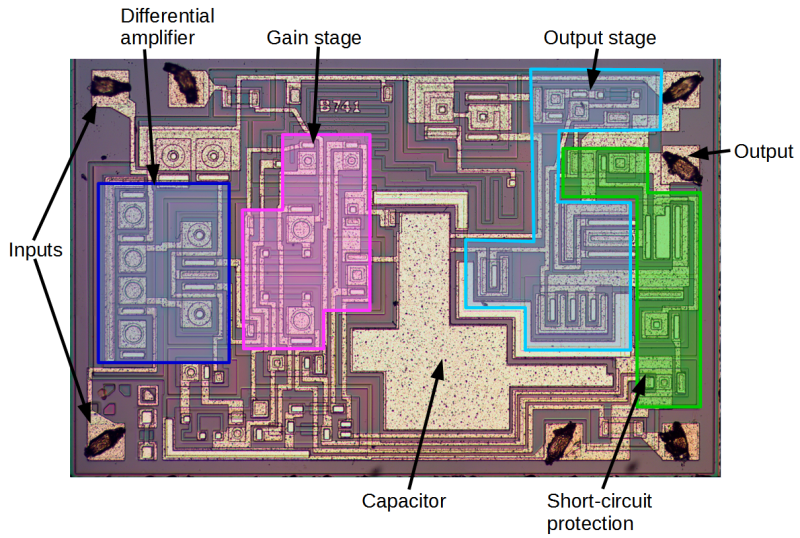
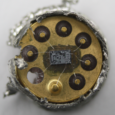 Rather than risk the boiling acid method commonly used to decap epoxy-potted ICs, [Ken] wisely chose a TO-99 can format to attack with a hacksaw. With the die laid bare for his microscope, he was able to locate all the major components and show how each is implemented in silicon. Particularly fascinating is the difference between the construction of NPN and PNP transistors, and the concept of “current mirrors” as constant current sources. And he even whipped up a handy interactive chip viewer – click on something in the die image and find out which component it is on the 741 schematic. Very nice.
We’ve seen lots of chip decappings before, including this reveal of TTL and CMOS logic chips. It’s nice to see the guts of the venerable 741 on display, though, and [Ken]’s tour is both a great primer for the newbie and a solid review for the older hands. Don’t miss the little slice of history he included at the end of the post.


There’s also the XL741 discrete component 741 kit from Evil Mad Scientist Laboratories: http://www.evilmadscientist.com/2014/the-xl741/
A lot of my first designs used this amp.
I love this stuff!
Ah, that takes me back to studying Analogue Electronics in Higher Physics back in 1986…the plastic tray of components, the breadboard, the +/-9V power supplies, the sharp crack and puff of smoke as Keith Marshall wires his op-amp up backwards and turns on the juice…
My favorite op-amp is the LM324, I given the understanding that it is quad 741.
The LM324 is not a quad 741. There is no single version of the 324 type, only a double (LM358).
The LM324 is well suited for battery (single supply) operation, as its inputs can go to GND (PNP input stage). I use it still quite often and have not used the 741 for decades.
There is a much more detailed analysis exactly like this but with a complete analysis of the transfer function as well, I think the photos may have been B+W but were higher resolution. My analog circuits teacher made us read through it as an assignment a long time ago, but I can’t seem to find it on the web. Does anyone remember who did the older writeup? I think it was from about 10 years ago.
Aaaah – reminds me of the fish tank heater controller I built when in school, using a 741 configured with a little bit of positive feedback to act as a comparator, and a single transistor acting as the temperature sensor. Didn’t know that the 741 occasionally can go into some sort of lock-up, where the output sticks to one of the supply rails until it is powered down. This caused the fish to pay the ultimate price. Anyone know anything more about that “lock-up” mode?
Awesome post! More, more!