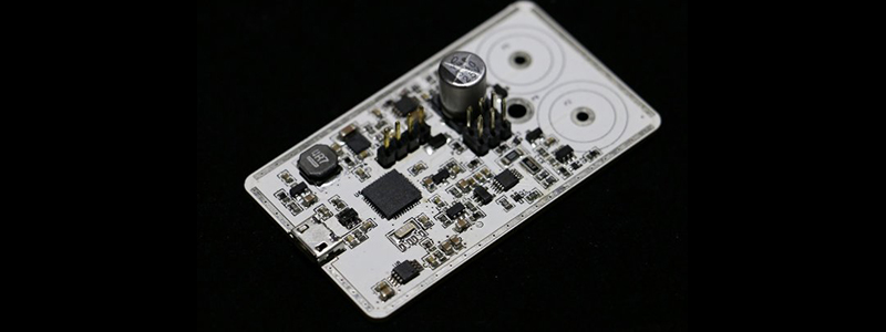
Ceramic capacitors are pretty much the pixie dust of the electronics world. If you sprinkle enough of them on a circuit, everything will work. These ceramic capacitors aren’t the newest and latest technology, though: you can find them in radios from the 1930s, and they have one annoying property: their capacitance changes in relation to voltage.
This is a problem if you’re relying on ceramic caps in an RC filter or a power supply. What you need is a device that will graph capacitance against voltage, and [limpkin] is here to show you how to do it.
Of course capacitance is usually measured by timing how long it takes to charge and discharge a cap through an RC oscillator. This requires at least one known value – in this case a 0.1% resistor – by measuring the time it takes for this circuit to oscillate, an unknown capacitance can be calculated.
That’s all well and good, but how do you measure capacitance against a bias voltage? EDN comes to save the day with a simple circuit built around an op-amp. This op-amp is just a comparator, with the rest of the circuit providing a voltage directly proportional to the percentage of charge in the capacitor.
This little project is something [limpkin] has turned into a Kickstarter, and it’s something we’ve seen before. That said, measuring capacitance against a voltage isn’t something any ‘ol meter can do, and we’re glad [limpkin] could put together an easy to use tool that measures this phenomenon.


As a side note, the circuit suggested by EDN will not work because of the capacitors ESR!
How high would the ESR have to be to disturb measurements significantly?
On the edn circuit? A few mohms only…
Could you clarify? The EDN circuit charges it at less than 1mA, which wold put it at under 1uV offset per mOhm of ESR.
Voltage dependence depends on the type of capacitor used. Type I dielectrics do not have a voltage dependence, or at least I have not seen it with any of the class I caps I use. Hell, I’ve got some caps that I have charged to nearly 2KV without changing their capacitance.
If you’re using a capacitor with a voltage dependence, you can always overrate it and get rid of most of the effect of the voltage dependence. Getting 50V or 100V rated caps is not that much more expensive, nor are they much larger. This is something that designers need to be aware of, but it is well known, and in the datasheet or type specification for the cap.
“Getting 50V or 100V rated caps is not that much more expensive, nor are they much larger.”
Neither does it have much improvement on the DC bias effect. https://www.maximintegrated.com/en/app-notes/index.mvp/id/5527
TL;DR – If you are using a 6.3V cap on a 5V rail, you are getting substantially less effective capacitance than the factory rating (a lot of us knew this part). The interesting caveat, here, is that replacing it with a 16V cap won’t necessarily help, as the voltage-coefficients of caps can vary greatly and are not advertised like, nor are they related to the the tempco’s, e.g., X5R, X7S, etc…
As you point out, the 80% value is only true for the more exotic dielectric materials they have to use to get enough capacitance in tiny SMD packages. I’m assuming you are not getting 2KV across a 1mm SMD capacitor. :)
Dave talked about this last year.
http://www.eevblog.com/2014/06/07/eevblog-626-ceramic-capacitor-voltage-dependency/
For most of the digital circuit decoupling, the high frequency impedance (which is dominated by the parasitics) not capacitance is what matters. Even for the better materials, when you crank up the electric fields (e.g. shrinking the package size down, applying DC bias comparable to their rate voltage etc), you’ll get some non-linear effects.
If you are worry about analog circuits, there are better type of capacitors (depending on application) than ceramic caps.
Agreed! I would -not- put one of those 10uF ceramic caps in anything that requires tight tolerances. For instance, bandpass/lowpass/highpass active filtering.
Would a plot from charging the capacitor from a constant current source not tell you everything?
You mean by watching the slope of the charge? Sure. The initial step will tell you the ESR. Collecting data points quickly enough will tell you the slope at any given voltage, which will tell you the capacitance at that voltage.
It won’t tell you everything as it can only tell you what’s going on at DC with one variable – voltage. It doesn’t not tell you about dissipation factor or frequency dependent losses/parasitics, piezo effects, temperature effects etc.
Of course, that is all this circuit tells you. You are talking lab quality instrumentation.
Go to the Kemet website and try the K-sim tool. This tool allows you to plot capacitance, ESR, impedance, inductance vs. frequency for the kemet capacitor product line. Very eye-opening!
How long before we see super low quality muntzed versions of these things in fleabay for $2 each