BB-8 is the much loved new droid introduced in the 2016 movie Star Wars: The Force Awakens, though in my case from the very first trailer released in 2014 I liked it for the interesting engineering problems it posed. How would you make a robot that’s a ball that rolls along, but with a head that stays on top while the ball rolls under it?
To make the ball roll, the answer most people found obvious at first was to use the analogy of a hamster wheel. The hamster running inside makes the wheel turn. In the BB-8 building world, which is quite large, the drive mechanism has come to be called a hamster drive, or just a hamster.
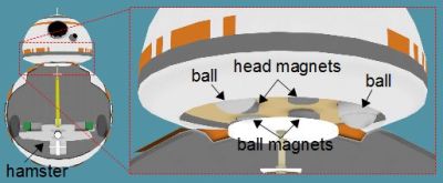
For the head, it seemed obvious that there would be magnets inside the ball, perhaps held in place near the top of the ball by a post extending up from the hamster. Corresponding magnets in attraction would then be attached to the underside of the head, and balls (also mounted under the head) would keep the head moving smoothly over the ball.
The magnet approach for the head has turned out to be the method used by all BB-8 builders that I’ve seen. However, the hamster has turned out to be only one of multiple solutions. Since the original debut many different methods have been used in builds and we’re going to have a lot of fun looking at each separate approach. It’s almost like revealing a magic trick; but really it’s all just clever engineering.
Note that for the actual movie, a combination of 7 or 8 props and CGI were used. The official working BB-8s that are shown at various promotional events were built after the movie was made and as of this writing, few details of their construction have been released. One notable detail, however, is that they aren’t using hamster drives.
Below are details of all the different BB-8 drive systems I’ve seen so far that have been built along with how they work.
Axle Drive aka Pendulum Drive
With an axle drive, an axle runs horizontally inside the ball across the middle halfway up. At one or both ends of the axle is a motor and the ball is attached to the motor’s shaft.
A large mass is suspended from the middle of the axle and is fixed to the axle. When the motors turn the ball, the ball rotates as expected. The large mass swings forward in the direction of the ball’s motion. But you may have expected the mass to swing backward.
If you’ve ever held a motor in your hand while turning something substantial or that’s difficult to rotate then you’ll recall that the motor wanted to rotate in the opposite direction. It’s dangerous so don’t actually do it, but imagine while drilling a hole in a piece of wood that you lock the motor to the on position and let go of the drill. If the wood is clamped down and the hole is tight enough, the result is that the drill will rotate in the opposite direction. The same happens here. The motor and mass rotate in the opposite direction that the ball rotates.
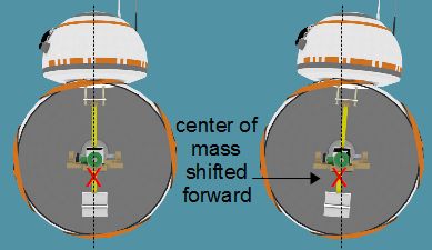
Another way to look at it that’s perhaps more correct is that when you swing the mass forward, that shifts the center of mass forward and the ball rotates in that direction. It’s for this reason it’s also called a pendulum drive (PDF) (section 2.2.4). The pendulum swings forward and the ball rotates in that direction.
Providing I have my physics right, the larger the pendulum mass, the less the pendulum should swing forward. This also happens more during the acceleration.
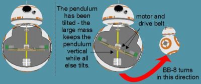
Turning is not done by the motors on the axle. To turn the ball, a mass is suspended from the center of the axle. The pendulum mass mentioned above can serve this purpose. A motor then swings this mass in either direction in line with the axle.
Swinging the mass to one side makes the ball tilt toward that side and the ball then moves in the direction of that side. Look carefully at the above illustration and you’ll see that the axle and ball are in fact tilted, while the pendulum stays horizontal due to its larger mass. This turning technique means the ball cannot rotate on the spot, but must be moving either forward or backward (though backward and forward lose meaning with a BB-8 since the head may be able to point in either direction.)
Forward and backward wobble can be minimized by again using the pendulum mass driven by the axle motors to swing the pendulum in the opposite direction of the wobble. To do this an IMU (Inertial Measurement Unit) is attached somewhere on the device. The IMU is a chip on a board that knows its orientation relative to the Earth (e.g. the BNO055 breakout board from Adafruit). Something like an Arduino takes that information from the IMU and uses it to turn on and off the motors to move the pendulum and gradually eliminate the wobble. The source code to do this is called a PID loop (Proportional Integral Derivative).
Sideways wobble can similarly be handled by swinging a mass sideways in the opposite direction, though I haven’t seen that done yet in any finished axle drive BB-8s. Either it hasn’t been handled or there was enough mass low down and relatively little mass high up, keeping the problem too small to notice.
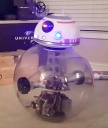
I’ve seen three completed axle drive BB-8’s online so far and an excellent one with copious making details is [Ed Zarick]’s shown in the photo.
The Hamster Drive
The hamster is typically a two wheeled vehicle that sits inside the ball, not physically attached to the ball in any way. Further support is usually given with casters or free turning balls extending out the front and back to contact the ball and help keep the two-wheeled hamster stable. Moving is done by rotating both wheels in the same direction.
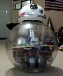
Turning is done by rotating the wheels in opposite directions. This means that each wheel has its own motor. This is called differential drive or tank drive, since it’s how two-tracked tanks turn.
Some have stabilized back and forth wobble by using an IMU to detect the wobble and driving the motors forward and backward in a PID loop. There isn’t a lot of room in the bottom of a hamster for a pendulum type mass that can be swung around for stabilization. However, the more fixed mass as low as possible, the more stable it tends to be.
You can see [Wayne Neumaier]’s hamster drive BB-8 shown in the photo during final testing before painting the ball. He has his two wheels near the bottom.
Hubless Wheel Drive
The hubless wheel has a similarity to the hamster drive in that there’s a vehicle inside that is independent of the ball. This design is best known as the one that [James Bruton] has done for his BB-8 version 3. The difference from the hamster is that with the hubless wheel, the so called vehicle inside is constrained to a track that’s a part of the ball. In the illustration below the sides of the ball are not shown, though they’re normally attached to the track. This track is what’s called the hubless wheel, as there is no hub at the center of it.
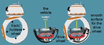
There’s a drive wheel that’s part of the vehicle that presses against the hubless wheel and makes it rotate (see the illustration). It serves the same purpose as the wheels in the hamster except that in this case there’s only one of them. The vehicle is constrained by a ridge all around the two sides of the the hubless wheel.
One of the reasons for this design is that the section of the ball that is the hubless wheel can be made with no seam in it.
With a normal ball there’s a seam where the two hemispheres of the ball come together and that can interfere with the smooth operation of the vehicle inside. With a hubless wheel drive, a central halo of the ball — the path the vehicle moves on can — be manufactured as one solid piece. The inside surface that the vehicle has to run on is smooth. Sure, there will be seams when the rest of the globe is added, but they will have no effect on the operation of the hubless wheel vehicle inside.
An advantage of this design over the others is also that the two sides of the ball can have access panels that open just like the BB-8 in the movie, even though the movie used props and CGI to do it.
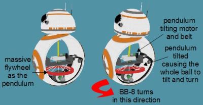
Turning is accomplished in the same manner as with the axle drive. The vehicle has a section that hangs down like a pendulum, and can be swung to either side. The mass of the pendulum illustrated here is a heavy flywheel (colored red). A motor can then swing that mass to either side to tilt the ball. And just as with the axle drive, tilting the ball causes the entire robot to move in the direction of the tilt.
Stabilization is done using a combination of techniques similar to the axle and hamster drives. For back and forth stability the vehicle in the track moves back and forth, countering wobble. And for side-to-side stability, the suspended mass is moved from side-to-side to counter that wobble.
The massive flywheel can also be rotated rapidly around its own axis, which causes the rest of the BB-8 to rotate in the opposite direction, allowing it the added trick of turning on the spot.
In the photo above you can see [James Bruton’s] hubless wheel BB-8 version 3 during final testing before doing all the cosmetics.
Omni Wheel Drive
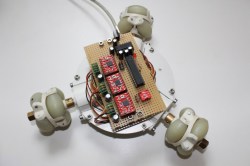
An omni wheel drive is similar to a hamster drive in that a vehicle drives around inside the ball but with the difference that the vehicle can move in any direction. This is done with three or four omni wheels, each with its own motor and oriented in its own direction.
I may have missed it but I haven’t seen any completed omni wheel drive BB-8 builds yet. I have seen one omni wheel drive (like the one shown in the photo) that drives a ball but with no head as yet. I’ve also seen one BB-8 with a working head that use omni wheels but as far as I can tell they’re used just as hamster drive wheels, though I may have missed some subtle difference supplied by the use of omni wheels.
Others?
There they are, and for me, knowing the many ways to bring BB-8 to life makes the robot builds themselves even more magical. I wouldn’t be surprised — in fact I’ll be delighted — if I’ve missed some. Let us know about any others you’ve encountered. These are very complex systems and I’d also love to hear your take on the subtleties of each. Leave those remarks, and any other BB-8 ideas in the comments below.


I was thinking of a design with a trio of gyros at right angles in the center on a gimbal mechanism, with all the electronics/weight stationary and evenly distributed. to move in any direction, just rotate the gyro mechanism inside the sphere, no other moving parts, except the head. I believe i saw a HaD article on a similar concept a long time ago.
IIRC, that concept was a cube no less, rolling around using the angular momentum stored up in 3 reaction wheels.
I think in an actual practical implementation, you’d want both the body and the head to be driven (like sneftel’s mention of the inverted pendulum below). That way if the parts ever got separated, they would be able to automatically reunite.
Here it is: http://hackaday.com/2016/03/25/resistance-is-futile-balancing-cubes-are-taking-over/
My thoughts exactly. These seem similar to reaction wheels used in spacecraft.
To me, the obvious “other” approach would be an inverted pendulum: The head itself contains all the drive circuitry, and simply balances on the body. To accelerate, the head moves slightly forward, at which point gravity starts it and the body rolling forward; it stays off-balance while accelerating (by matching the speed of the body), then zips back up to the top of the body.
Like a circus performer walking on a ball, basically.
a variation of this:
http://spectrum.ieee.org/image/MTU3NjUwMA
I really like this idea. The most versatile might be a combination of this and one of the other methods. Both working together would make for better starts/stops and hill/terrain handling. Working in opposition would give the effect seen where the head is off-center like when he’s looking up or around a corner.
Plus it would allow for a thicker shell on the main body being that you’re not relying as much on that mechanism to provide the motion. That would give one the ability to embed other effects like the lighter, cattle prod (if you dare), and hidden compartments.
James Burton has built 3 BB-8s so far. This was his first. Go watch his youtube videos. Very well put together and not at all borning.
In the graphics you’ve got, the pendulum is attached to the head. BB peers around objects, so there has to be some mass unrelated to the pendulum. I’m picturing the mass having a hinge and another motor in order to be able to push the mass front to back compared to the head stalk piece. This would only let the head tilt forward and back unless there’s also a mechanism to turn the whole pendulum inside the ball.
Yup. To keep the diagrams simple and easy to understand I decided to ignore the independent head movements and focus just on the drive systems. For the axle type, for example, it’s just a matter of having the head’s post extend down past the center to its own separate counterweight and have a separate motor to control it. The counterweight is for minimizing the amount the head upsets the body. Ed Zarick did that with his design http://www.edsjunk.net/wordpress/bb-8-parts-and-instructions/.
I think James Bruton’s v1 build is purely omni wheel driven. But from the head.
That was his first version, it worked, but not very well. It couldn’t really stand in one place very well, and hard floors made it worse.
I’m just remembering that BB-8’s head leans forward into movement, and trying to reconcile that with the drive system diagrams. Maybe the head just has more than one position.
I skipped drawing in the head movement mechanisms in favor of keeping the drive systems easy to visualize. For the axle type you could have the head on a separate post that has its own counterweight and motor. The counterweight is for minimizing the affect of the head on the ball since when the head is forward, that would tend to tilt the ball forward.
Yea the build I haven’t seen yet is one that shifts the head independently of the body. Currently the head counters the ball’s drive mass that causes the forward movement (a problem I encounter with my Sphero BB8 on thickish carpet.) I’d love to see an omnidrive head that is controlled independently but I bet the first iteration will just control the arm that is usually stationary inside the ball.
Also, technically all of the drive systems mentioned move the ball with the same principle of the pendulum. The wheels drive the mass up the wall of the ball and gravity pulls it back down levering the ball forward.
Here is my take on pendulum drive: http://essentialscrap.com/sphere/
Controlling it is harder than I expected; it could easily start tumbling, especially when trying to turn. Also turn radius ended up very long.
I like the remove control. You could hide it as the top of a walking stick and no one would know who’s controlling the ball.
I’ve been working on the Omni wheeled version of this since before BB8 came out. My inspiration was the New Pet XKCD comic (from back in 2008). http://www.xkcd.com/413/
I started a build log here on Hackaday.io, but have been very swamped with work, so its been slow going keeping it up to date. https://hackaday.io/project/1621-randall-bot
I have more information on the entire system on my old website. https://sites.google.com/site/engineeredbyluck/home/for-fun-projects/hamsterballai
Most recently I’ve been tackling the other issue with BB8, that no one has done anything active with the head unit. I aim to do some vision processing and implement a basic AI. The latest step was powering the Pi Zero (which replaced my custom ARM board design) by wireless induction power. https://www.youtube.com/watch?v=A_yJUGsATo4
…you know, just to toot my own horn a little bit…
Hi Steve! Fantastic article. The detail and illustrations are great! One minor correction: Isn’t an IMU an Inertial Measurement Unit?
Hey, good seeing you here! Thanks and thanks, fixed.
haven’t put too much thought into this (which will probably become obvious rather quickly) but what about making the ball it’s self the motor?
if you were to put magnets in the ball and utilize an array of electro magnets inside i’d think you could pulse them off and on for movement, and keep the head moving totally independently of the drive as it would have its own set of magnets.
i wonder if you could even go simpler on the inside by having a disc or series of rings of some sort that would always be spinning that could expand and contract to reach the point where it “grabs” the outside magnets. could be a decent use of bucky balls, haha.
As I was reading through the article that exact concept came to mind and like all good ideas I got the last comment and someone had beaten me to it :)
All of the designs work by causing a weight imbalance relative to the balls outer surface contact. I don’t see where your weight imbalance is occurring. Can you explain further?
What about an empty rigid body sphere, with a weighted 3-way drive within/at the edges of the head?
Very stupid method you could do;
The whole Inner surface of the sphere is covered in electromagnets.
These magnets pull a heavy inner ballbaring about, which shifts the weight making it move.
Some controller, as well as a gyro, would probably be needed to work out which electromagnets to use when.
How’s about a 3 or 4 legged delta robot internal to the ball which shifts the mass continuously as the ball rolls. Head is a separate wheeled unit individually accelerometer controlled. The problem, well one problem, would be identifying and controlling how fast to move the mass to enable a closed loop control system.
Neat idea. I had to look up delta robot to see what you meant but before I did I was thinking you might have meant a walking robot, which is another neat idea. But the head is even more difficult to do there.
With the delta robot you could still have a post going up from the delta to magnets to manage the head. The main body of the delta robot would have to be held stationary in the ball’s center relative to the ball so that its reaction to the movement of its own mass doesn’t affect the ball’s rotation. That could probably be done with at least four casters on the ends of rods extending out from the delta’s main body in the horizontal plain.
Obviously the best way to drive would use a hamster.
The ‘radio to hamster interface’ could be difficult to implement..
Arduino driving a servo…
…connected to a carrot.