Every machine has its own way of communicating with its operator. Some send status emails, some illuminate, but most of them vibrate and make noise. If it hums happily, that’s usually a good sign, but if it complains loudly, maintenance is overdue. [Ariel Quezada] wants to make sense of machine vibrations and draw conclusions about their overall mechanical condition from them. With his project, a 3-axis Open Source FFT Spectrum Analyzer he is not only entering the Hackaday Prize 2016 but also the highly contested field of acoustic defect recognition.
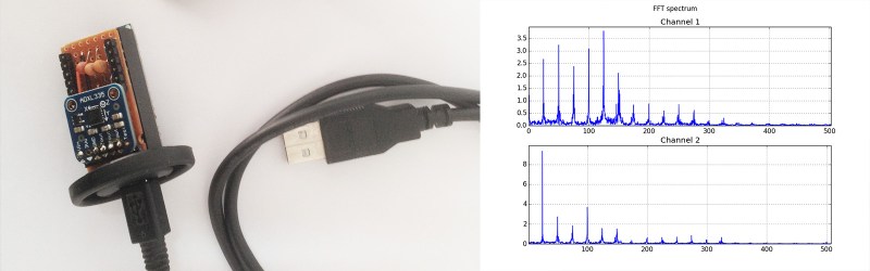
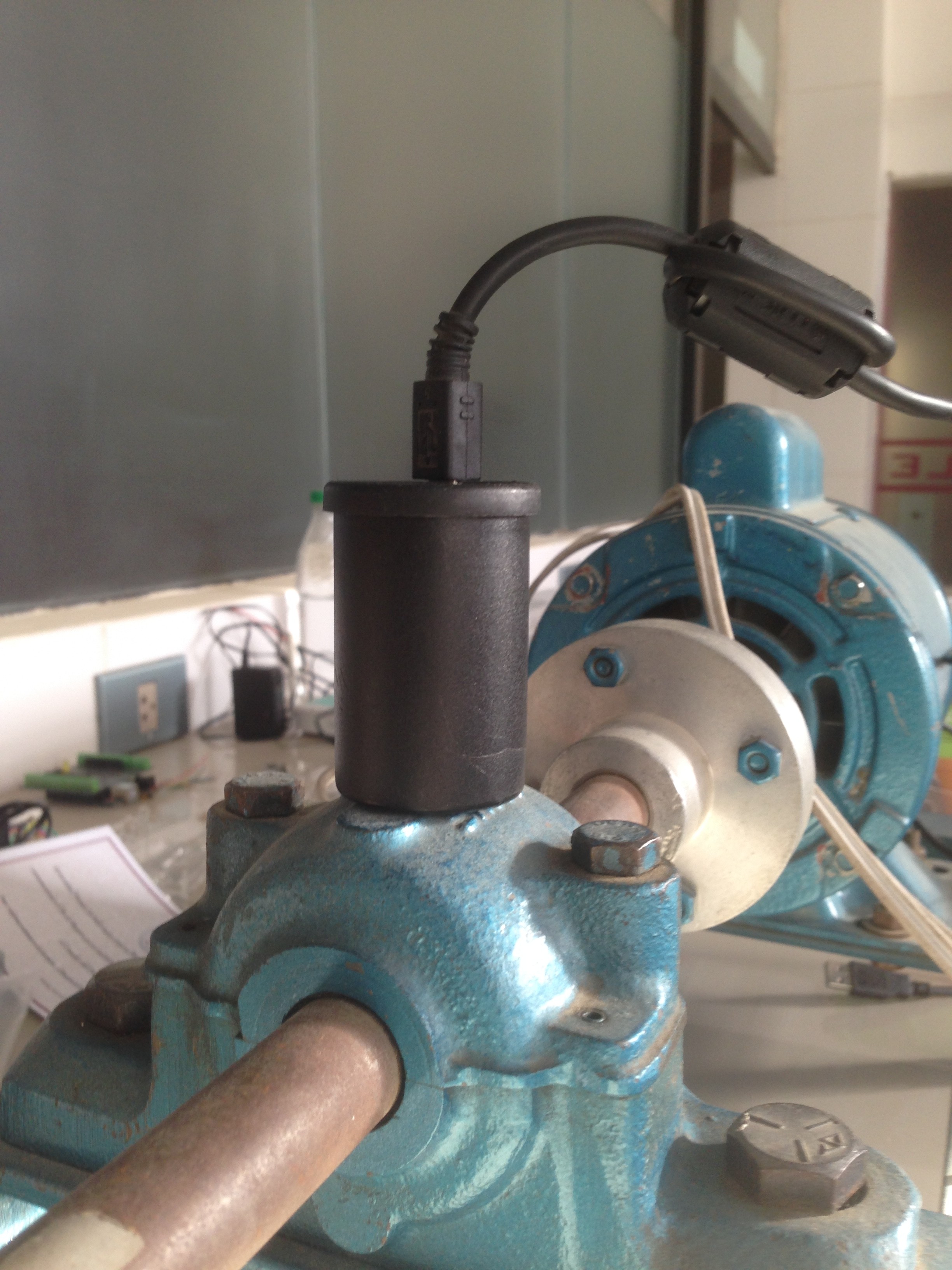 For the hardware side of the spectrum analyzer, [Ariel] equipped an Arduino Nano with an ADXL335 accelerometer, which is able to pick up vibrations within a frequency range of 0 to 1600 Hz on the X and Y axis. A film container, equipped with a strong magnet for easy installation, serves as an enclosure for the sensor. The firmware [Ariel] wrote is an efficient piece of code that samples the analog signals from the accelerometer in a free running loop at about 5000 Hz. It streams the digitized waveforms to a host computer over the serial port, where they are captured and stored by a Python script for further processing.
From there, another Python script filters the captured waveform, applies a window function, calculates the Fourier transform and plots the spectrum into a graph. With the analyzer up and running, [Ariel] went on testing the device on a large bearing of an arbitrary rotating machine he had access to. A series of tests that involved adding eccentric weights to the rotating shaft shows that the analyzer already makes it possible to discriminate between different grades of imbalance.


Making this option affordable is a great project, and there is a lot more you can do with the data too.
You’ll find a few choice papers here: https://www.google.com/search?q=machine+learning+detecting+vibrations+faults
Nothing better than the experienced ear. This is worthy project though.
Except, you know, the technology.
https://www.youtube.com/watch?v=Z59AnkxekfI
This is arguably my favorite movie… Every scene is quotable
The setup is probably good for frequencies under 10Hz. On the upper frequency range it probably measures some bogus resonant frequencies of the probe unless the accelerometer is connected to the DUT using very rigid joint. Probably the bare accelerometer glued directly to the magnet and dipped in a drop of epoxy resin will do the trick. But in fact, I am not quite convinced that the MEMS accelerometer is the best way to sense vibrations of very small amplitudes.
it isn’t.
for this level of accuracy, much cheaper to slap some piezos on the device under measurement
one still need to calibrate them, of course
May be geophone, essentially a moving coil construction for detection seismic vibrations, would be more suited for this?
https://en.wikipedia.org/wiki/Geophone
Vibration data here may exhibit a normal distribution (time invariant). Perform some STL and run it through some Machine Learning system (i.e. Support Vector Machine). I believe this method has been done for year in industrial anomaly detection. Great project!
Now he can work on a low cost rotational balancing system. That’d be swell :)
This looks like a similar sort of thing to a system called HUMS (health and usage monitoring system), used in helicopters. It’s basically a whole lot of vibration sensors all through the gearbox and engines, and after each flight the engineers download the data and look at it on a spectrograph. By looking for trends or step changes in the spectrum they can see if any components are about to fail, and narrow down the source of the problem by looking at both the sensor, and the frequency of the abnormality. Most of the frequencies present are (harmonics of) the gear meshing rates.
I could explain to me how I put the accelerometer on cable
I imagine that capacitors are used air filters, how many they are? How many microfarads have those capacitors?
Hi Moritz.
Awesome work and great project! It may be worth to noticed here that I have designed
3 AXIS USB ACCELEROMETER. I think that it may be very useful for this project. It is compact and ready to use out of the box. What is more it has a set of commands to set sampling frequency and data range.
Please check it here: https://www.tindie.com/products/electromake/3-axis-usb-accelerometer/