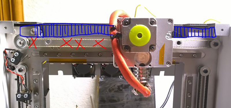
Today, your average desktop 3D printer is a mess of belts, leadscrews, and pulleys. For his Hackaday Prize entry, [DeepSOIC] is eliminating them entirely. How’s he doing this? With a linear stepper motor.
Search Google for ‘linear stepper motor’ and you’ll find a bunch of NEMA-bodied motors with leadscrews down the middle. This is not a linear stepper motor. This is a stepper motor with a leadscrew down the middle. The motor [DeepSOIC] has in mind is more like a mashup of a rack gear and a maglev train. The ‘linear’ part of this motor is a track of magnets perpendicular to the axis of the motor, with alternating polarities. The ‘motor’ part of this motor is a carriage with two field windings. It’s an unrolled stepper motor, basically, and could run a 3D printer much faster without as much slop and backlash.
Right now [DeepSOIC] is in the experimental phase, and he had a plan to print the axis of his linear stepper in ferromagnetic filament. This did not work well. The steel found in electric motors has a magnetic permeability of about 4000, while the magnetic permeability of his brand of ferromagnetic filament is about 2. Even if the idea of printing part of a motor was a complete failure, it was a great success at characterizing the properties of a magnetic 3D printing filament. That makes it a great entry for the Hackaday Prize, and a perfect example of what we’re looking for in the Citizen Science portion of the Prize.


Meh. This is nothing new – you can go out and buy a real linear motor. In fact, many precision industrial machines use them
I feel like you skipped reading something…
maybe the article?
Else, please give a link to cheap linear motors.
Agreed. Stepper motors are stupid toys if you want speed, precision, and repeatably.
If you want cheap stick with your toys.
Has anyone tried using geared linear rail with nema? I think It will be less expensive than linear stepper motor.
Racks have been done. Drawbacks are linearity and backlash, among others. Perfect gear tooth form and positioning will give perfect linear motion. Real world, not so much. There will be cyclic non-linearity with each tooth, as well as any due to imperfect pinion form, plus still needed linear guides that take and control side loading (gear teeth push apart under load) that is not uniform and of significant magnitude. It can all be accounted for, and good results are had in the real world, but lead screws are more accurate and have higher load capacity with less positional correction needed, for equivalent or lower price at a given performance level. Backlash can also be corrected for or eliminated more easily.
Offhand, it feels like something akin a piezo inchworm-motor:
https://en.wikipedia.org/wiki/Inchworm_motor
or running a rotary-stepper driven worm-gear against a rack would end up being much simpler, than trying to print ferromagnetic filament.
Alternatively, perhaps you could do selective heating (laser cutter) to the Curie point,
on a steel bar in a strong magnetic field, then flip the field and “cut” the alternate poles.
That laser heating idea sounds promising to me. :D
I wonder, how well that would work on laminated transformer core?
Extra points if he can remove the need for a linear bearings too.
Maybe levitate the print-head in 3D, using strong magnetic fields and a webcam for position feedback?
Or a similar system to a vernier caliper..
Or maybe he could just move the print head by hand?
I’m afraid there has to be a linear bearing in one form or the other =)
have a look at the Festo ELGL-LAS it works without mechanical bearings. Instead it uses compressed air. The cool thing about that is, if you turn of the air the carriage is blocked and can not be moved anymore.
Considering there aren’t any gears, there should also be zero backlash. However, it would be very hard to get reasonable precision of out such a setup, because the step size is relatively large. I’d think it would be hard to make something better than 0.2mm per step. Microstepping will improve this a little, but only by about a factor of 4 or something. Of course you can do many more microsteps than that, but 256 microsteps doesn’t actually give you 256x the resolution or precision.
Most industrial linear drives are actually 3-phase permanent magnet servo drives, using very high resolution linear encoders to measure the actual position for closed-loop control.
Might it not be easier just to hand-place the components, then take care of the inaccuracy with feedback? Rather than trying to print exactly-spaced coils.
Would be my way too. I d’ use linear position feedback from something like the AMS linear hall sensors and precision magnetic strip. It’s gonna cost a few 10$ per axis for that chip and strip i think. If you really want an adventure, you could probably try to use optical sensors from cheap PC mice and figure out how to use them for position feedback.
could use the encoder strips used in cheap printers, basically the linear version of the quadrature encoder in an old school mouse with a ball.
I was watching this video about some very sexy linear motors just yesterday: https://youtu.be/jleS4nog5UQ?t=61
I want them, all of them, not sure for what, but I want them. But I think I’ll need to get a second job first…
Awesome idea! Next, let’s 3D print an ARM MCU too!
It may be possible to use something similar to a linear switched reluctance motor, except using pole pieces in the stator which have alternating permanent magnetic fields.
If you’re interested in linear drives, you might enjoy this paper by a group of Romanian professors. They have an interesting approach using an electromagnet to “gate” the magnetic field of a permanent magnet. Full article here:
http://citeseerx.ist.psu.edu/viewdoc/download;jsessionid=C8717A8B34E356740C14E9F8A5AC99EF?doi=10.1.1.301.6813&rep=rep1&type=pdf
i wouldn’t use the ferromagnet-filament.
just print a linear rail with lots of holes in it and stuff some neodym-magnets with altering orientation in it.
To improve the magnetic flow add a metal sheet underneath,
For the coils print a holder again and put some screws in it.
Add some wire around the screws to get the coils.
I’ve made something similar already. The problem here will be the resolution of the position and the max force you get, however this can be solved by building a controller including some kind of position-encoder.
The advantage of the linear stepper is you dont need feedback and can use any stepper drive. If you are going to throw on an encoder you might as well just design it as a 3 phase linear motor and use one of the multiple different drives out there. Or just buy some used motors/drives off ebay. I picked up a couple of Parker 6″ travel slides and drives for $500 each off ebay for work. They have 10nm resolution. Pretty insane.
NANOMETERS?! Man, did you win or what!
Yep, nanometers. Luckily the drives are programmable and I was able to lower the resolution when using step resolution x20 so it is usable off a parallel port with Mach3 driving them. Still real slow but it has the accuracy I need for the job I need to do.
Calling bullshit or marketing department on that. How do you have 10 nanometers optical encoder when the wavelenght of ultraviolet light is 400 nm?
The device might have internal “precision” of 10 nm per step, but no way it does what would be ten hydrogen atoms per step. No. Friggin. Way.
The encoders have a sinusoidal output and use interpolation to get the final resolution. Renishaw makes them down to at least 5nm resolution.
or you could do something actually smart, like use a closed loop system with BLDC Servo
All this work on better slides and motor control ignores the fact that the primary bottleneck in printing is the extrusion and more importantly the joining/cooling rate of the extruded material. If one tries to print something as simple as a spur gear about 1in diameter, the acceleration settings limit your moving speeds a lot, but if you could go much faster you would get a horrible cylinder instead of that gear.