There are a proliferation of cheap digital meter modules available online for pocket money prices. Current, voltage, frequency, or combinations thereof can all be yours for just a few dollars and a wait for shipping. Unfortunately though these meters are all self-contained units. They do not have a serial port or other interface through which you can log their readings.
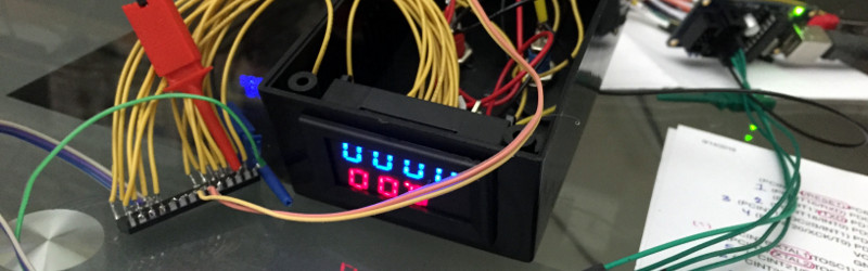
This failing was not an obstacle for [Scott Harden], though. He simply added a Bluetooth interface to his combined voltage and current meter module by using an ATmega328 microcontroller to capture the signals sent to the module’s display LEDs and interpret them into readings for his Bluetooth module. He details the process of reverse engineering the meter, and his build. The result is an intriguing mess of wires with a DIP ATmega hanging on their ends. But it performs the task requested of it admirably and when mounted in a project box you would not know what lurks within.
He has made his code for the project available in his GitHub repository, we can see that this could be a valuable technique for use with other similar displays. In the video below the break he gives us a full run-down, as if his comprehensive write-up was not enough.
[Scott] is a prolific hacker whose work we have featured before quite a few times on these pages. Most recently we had his PC frequency counter, but just a couple of his other projects we’ve seen are his USB interface for an aged counter, and his single chip Hellschreiber transmitter.


In the early days of IC DVMs, Motorola had an IC that worked with a separate IC for the display. So it was better suited for connecting o computers, though small computers weren’t too common at the time. But things moved fast, the desire for DMMs meant better integration, and then they were all single IC. Much better for making meters, much harder for interfacing.
Michael
The two-chip approach was useful in the days when the display technology might change, when the designer could change the BCD-to-display decoder chip separately from the DVM chip. E.g. fit a BCD-to-Nixie decoder one day and a BCD-to-seven-segment chip the next. I have an AVO DA114 that uses a separate Nixie driver chip, fed with BCD from the DVM chip. There’s also a 7447 BCD-to-seven-segment chip in some of the Fluke LED DVMs (the 8000A, I think, has this setup). The BCD signals are indeed a useful place to add an interface.
I think the reason was that in these days the separation of analog and digital circuitry was the best (only?) means to eliminate digital interference in the analog part. The two chips could even have needed different processes.
I have 9 Intersil ICL7109CPL 12 bit ADC MPU compatible IC’s in my parts box. It is probably similar to the Motorola IC you mention.
That’s true, but most of these cheap meters today are designed around a microcontroller. Often even some Chinese 8051 derivative, e.g. from Holtek. So basically you add two more CPUs (Atmega and Bluetooth chip) to the first one. This could be done much more elegant. But perhaps not cheaper. :-)
Did I miss the newsflash where the planets entire supply of ADC chips got eaten by space zombies or something?
Think outside the specific project at hand – This hack could be applied to any manufactured device that has a simple digital display/output, but perhaps you want to make it “smarter” – add data logging, wireless connectivity, etc. While a voltmeter/ampmeter could easily be built from the ground up, think about modules that are part of bigger machines/appliances. For example remotely monitoring a battery charging system. The existing unit has expensive and complicated charging circuitry, and a microcontroller loaded with charging algorithms. The unit has segment displays as well as LEDs to display and indicate status. In this situation it would make a lot of sense to leave the unit performing as is, tap into the display wiring, and process the data. Processed data can then be logged, or broadcast via wifi or bluetooth
Word.
https://hackaday.com/2016/06/07/hacking-a-fluke-multimeter-to-serve-readings-over-wifi/
(And I’ve been meaning to do it for ages to one of those laser time-of-flight rangefinder measuring-tape thingies.)
Well now y’all put it like that I’ve got a hankering to dig out the hotwheels radar gun.
yeah, I could sacrifice one of mine to this task.
Hot Wheels Radar Gun is an LCD display, so a bit trickier to monitor it’s 7-segment interface. Besides, the radar section gives a frequency output that is proportional to the speed of the object being tracked to the microcontroller that handles the display. So it’s a lot easier to design an interface that tracks that single signal going in, rather than the display outputs..
FYI, Here is a good HotWheels Radar Gun mod page
http://www.edparadis.com/radar/
A DMM is more than an ADC. If you’re going to bother implementing all the rest, then you’ve built your own multimeter. This way ignores all that stuff, takes the data where it’s already digital and just needs a bit of rearranging. Much easier to debug, and he doesn’t need to understand high-precision analogue electronics, as well as the high-voltage safety and ammeter shunt and all the other stuff.
Except this isn’t a DMM. It’s a cheapest MCU with a built-in ADC one can find in Shenzen, connected right over the voltage to be measured – meaning the whole “meter” is redundant considering the glue MCU could have done the exact same thing.
i have a very similar looking panel meter that has UART pins used for calibration … sending it an H (i think it was an H) reported back the raw ADC values
fuzzing it to try and find out more ended up bricking it so be careful
It’s an interesting approach for the situation where you have no choice. I can see it being useful for the ammeter portion as the current shunt would require a high impedance amplifier to boost the DC signal off it to a level an ADC could read.
Otherwise, the ADC in the ATMega328 with a voltage divider would probably suffice on its own, and if you need a read-out, if you have enough pins to sense a display reading, you also have enough pins to drive the LEDs too.
Try measure a negative voltage by a microcontroller ;)
It is a matter of using a voltage divider (or opamp circuit) to level shift and scale the input. Yes, you can level shift +/- 3.3V into 0-3.3V with just 2 resistors..
But just to get back in your comfort zone, look back a few months for the hacklet “How to use an Arduino as a resistor” …. ;-)
The module actually uses the STM8S 8-bit microcontroller with its onchip 12-bit ADC, so there are already necessary voltage divider to scale the input voltages suitable for an ADC. So it is pretty easy to hook up a uC with a decent ADC. The only issues is that the display might disagree with the reading due to linearity/Offset etc..
There are even a programming/hardware debug breakout on the upper left hand corner and possible a 4 pin TTL serial interface? Programmer/hardware debugger is a $3 St Link clone from China.
Yeah, this. I had a look in the back of some panel meters recently and they’ve all got an STM8 with the programming headers are exposed. Even if the code in them is locked/unreadable, you should still be able to flash your own code to it since I don’t think OTP parts are a thing anymore.
There was a project that reprogram a single channel to be used as a display and has source code on github.
There are actually protection bit on an ARM chip that prevents reprogramming and cannot be deactivated as full chip erase is disabled. OTP is very much alive by design. Not sure if this applies to STM8. Even if it does, it is pretty trivial to replace one with a $60 hot air removal tool or simply cut off the pins of the TQFP with a box cutter.
I bought a cheaper voltmeter module that uses some other 16-pin chip instead of the STM8. No programming interface on those.
Especially a current shunt does NOT need a high impedance input. It is a very low impedance source. Of course it needs some amplification. But the most important feature of this amplifier is a low offset voltage – or some means to compensate it.