For most of us, our touch-screen smartphones have become an indispensable accessory. Without thinking we tap and swipe our way through our digital existence, the promise of ubiquitous truly portable computing has finally been delivered.
Smartphones present a problem though to some people with physical impairments. A touchscreen requires manual dexterity on a scale we able-bodied people take for granted, but remains a useless glass slab to someone unable to use their arms.
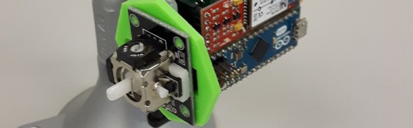
To the smartphone itself, the device appears as a standard Bluetooth pointing device, while at its business end the joystick and pressure sensor both interface to a Bluetooth module through an Arduino Micro. The EAGLE board and schematic files are available on the project’s hackaday.io page linked above, and there is a GitHub repository for the code.
Technology is such a part of our lives these days, and it’s great to see projects like this bridge the usability gaps for everyone. Needless to say, it’s a perfect candidate for the Assistive Technology round of the Hackaday Prize.
Hard drives work by spinning platters full of magnetized data while a read/write head very quickly harvests or changes bits as needed. Older (or perhaps cheaper) drives spin at 5400 RPM, better drives spin at 7200 RPM, and elite drives (that mortals like you never shell out for) spin in the 10k-15k RPM range. This spinning is thanks to a sweet combination of a bearing and a brushless DC motor.
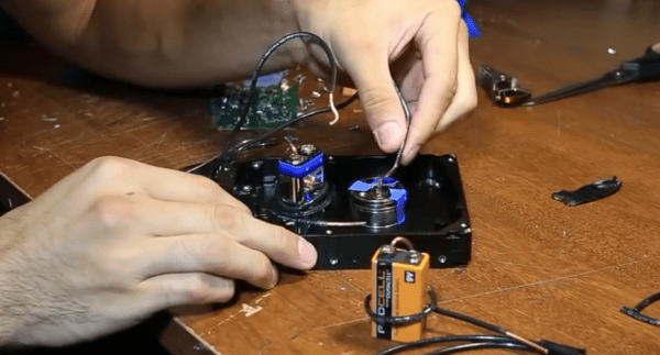
Unfortunately you can’t drive a brushless motor without a brushless motor driver. Well, of course that’s not absolutely true — and [Tommy Callaway] has certainly hacked together a crude exception to the rule. He’s using a 9-volt battery and some blue painters tape to drive a brushless motor.
Brushless motors do their thing by placing permanent magnets on the rotor (the part that spins) and placing multiple stationary coils of wire around it. Brushless motor drivers then energize these coils in a vary carefully timed pattern to continuously push the rotor magnets in the same direction.
[Tommy] wired up his 9V to one of these coils and observed that it holds the rotor in position. He then began playing around with different ways automatically break the circuit to de-energize the coil at just the right time. This means using the spinning center of the hard drive as part of the circuit, with blue painter’s tape in alternating patterns to create the timing. Is this a brushless motor driver, or has he just re-invented the brushed motor?
If this workbench trick leaves you wanting for some hardcore BLCD action, you can’t go wrong with this $20 offering to push motors at very high speeds.
It was quite a surprise to learn that thermite isn’t just rust and aluminum powder, but describes any combination of metal powder, metal oxide, and optionally fuel mixed together in a reactive ratio. [sciencewithscreens] shows us some of the properties of a copper (II) oxide based thermite.
We can only assume he has a thing for copper as an element. After growing his copper crystal it wasn’t long before he followed a winding road of copper based experiments and found himself with a supply of copper (II) oxide after rendering it from common household chemicals. He had two missions for it. The first was to witness an unfettered copper oxide based thermite reaction. Some had assured him it was practically explosive. The other was to attempt refining pure copper using the reaction. That would be pretty cool considering it all started out as an impure blend of laundry detergents and fertilizer.
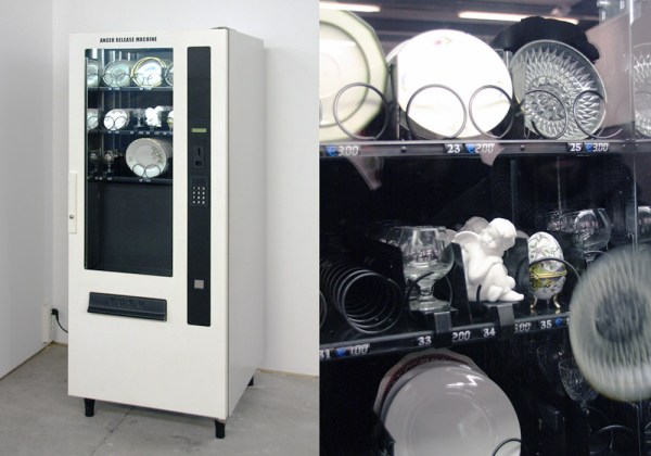
Is your temper hard but brittle? Meet the Anger Release Machine: a ware-dropping spiral vending machine stocked with precious porcelain.
There’s a bit more engineering and user experience design behind [Yarisal & Kublitz’s] art installation than meets the eye. The Anger Release Machine drops your purchase from dangerous heights, but like every passive aggressive vending machine, it also does its best to infuriate you using controlled disappointment. Insert a coin, see the steel spirals turn, and just when you’re already dying of the suspense…
A few years ago, I wrote a few columns titled Making A Thing. These columns were a tutorial of sorts for several different 3D modeling programs. This column wasn’t meant to be a complete guide to modeling an object in OpenSCAD or SolidWorks, it was just step-by-step instructions on how to make one specific thing with one specific piece of software.
More than a few people in the Hackaday community found this column useful or at the very least an interesting pedagogical device. When starting out with any kind of productivity software, you don’t need to know how to do everything, you just need to know how to do the most common tasks.
Since the Making A Thing column was so popular, I felt it was time to revive this idea with another design task we often face. As you have already guessed, we’re going to be making printed circuit boards. Continuing the unique tutorial format created in the previous iteration of this column, Making a PCB will build one specific circuit in multiple EDA suites.
The Circuit
The entire concept of demonstrating how to build one thing in a specific software package necessitates a model thing. Before I even begin writing the first Making A PCB column, I need to design something that’s sufficiently complex but still relatively simple, and something that’s hopefully somewhat useful. Breakout boards are extremely simple, perhaps too much. In the course of these programs, I’ll need to demonstrate how to make a part in each specific software suite, so fewer pins are better.
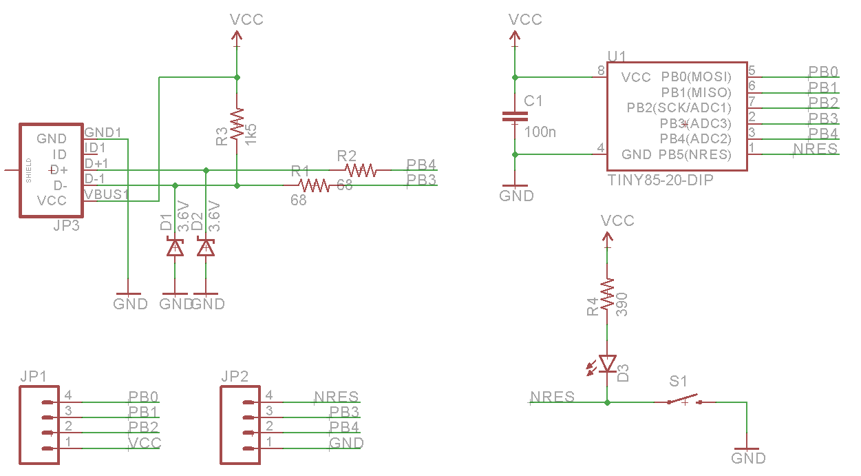
Lacking any creativity of my own, I’ve settled on a very small ATtiny85 Arduino derivative from Tim a.k.a. [cpldcpu]. Tim’s Nanite 85 is an exceptionally small Arduino-compatible board based on the ATtiny85, complete with a USB port, LED, and a few pins of I/O. It’s simple but sufficiently complex to give an introduction to a PCB design suite.
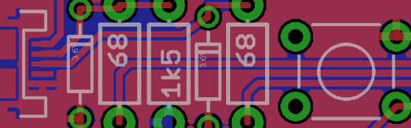
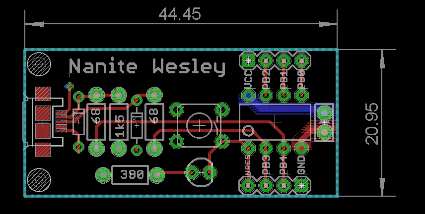
I’m not going to outright copy Tim’s Nanite 85, though. It’s much clearer if parts aren’t stacked on top of each other, and I’d like to give myself a little breathing room on the layout. I’ve redesigned the circuit of the Nanite 85 to use mostly through-hole parts on a slightly larger board. I’m calling my version the Nanite Wesley, and if you get that reference, thumbs up for you.
The schematic for the Nanite WesleyThe Nanite Wesley board. Copper pours not shown
Is this how a board should be laid out? No, absolutely not. I could probably do this as a single-layer board. This is a very inefficient layout, and I like rounded corners on my boards. It’s good enough, though, and it works. This is meant to be a tutorial on how to use a PCB design package, not a tutorial on how to design a PCB. Your criticisms in this regard are noted and ignored.
What These Tutorials Will Consist Of
You cannot use a PCB design package until you know how to make a part. Yes, Eagle has wonderful libraries for almost everything you can imagine, KiCad has plenty of parts on the Internet, and if you’re using a cloud-based PCB software, almost everything will be provided for you. If you make a PCB, eventually you’ll have to make your own part, though, and each tutorial will begin with making a DIP-8 ATtiny85. Everything else on this board is a jellybean part. Either way, the process of making a part and package for a Zener is the same as making one for a microcontroller.
The next part of the tutorial will consist of schematic capture. This means placing the parts in the schematic, drawing wires between the pins and pads, and naming them. From there, it’s time to actually make a board, and this means dropping the parts down, putting traces between all the pins, doing the board outline, pouring copper, and mechanical considerations.
With the schematic and board designed, it will be time to send it off to a fab house. For Eagle and KiCad, this is easy; OSHpark accepts Eagle .brd and KiCad .pcb files, but this is cheating. We’re going to use CAM to generate real Gerber files. If you make enough PCBs, you’ll have to learn it eventually.
Caveats and Poor Design
There are a lot of things that go into making a ‘proper’ PCB, including isolation, direct traces to decoupling capacitors, making sure pixies don’t go around sharp corners and a thousand other items that won’t be discussed in these tutorials. There’s a reason I won’t be discussing this. This is a guide on how to use a PCB design tool, not how to design a PCB.
What else should I do?
As you can probably guess from the schematic above, the first PCB software I’m going to cover is Eagle. KiCad is on the list, as is Fritzing, Altium CircuitMaker, and OrCAD. In the interests of putting PCB design in a historical context, I have a copy of AutoTRAX and an old DOS machine. I’ll also be covering a few of the cloud-only design tools such as Upverter.
That’s enough software suites to get started, but as with the Making A Thing series, I’m going to be looking for suggestions from the peanut gallery. I can’t change the circuit I’m making, as that’s the entire point of this series, but I am looking for suggestions on other tools to cover. What else can I do? Want me to grab a piece of copper clad board, sticker overlays, and some photostatic film? I can do that. Are you at a web-based EDA startup, and want some free advertising? Leave a note in the comments.
Thanks to our efforts to slowly improve the backend of Hackaday, you’ll be able to access all the Making A PCB In Everything posts from the series list below.
Last time I showed you how to expose a web service on a Raspberry Pi (or, actually, any kind of device) by using a reverse proxy from Pagekite. On your Pi, you just need a simple Python script. However, it also depends on the Pagekite server, which isn’t always convenient. There are limits to the free service, and you don’t control the entire thing. The good news is twofold: the same Python script you use to set up the client-side can also set up a server. The other good news is the entire thing is open source.
In practical terms, then, if you have a computer that is always on and has an IP address that can be found on the public internet, you can run your own Pagekite server (they call it a front end) and service your own backends.
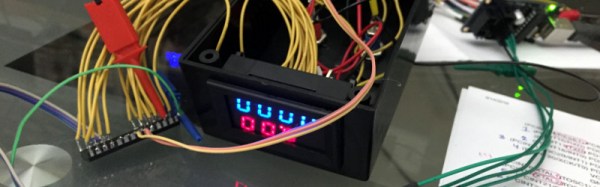
There are a proliferation of cheap digital meter modules available online for pocket money prices. Current, voltage, frequency, or combinations thereof can all be yours for just a few dollars and a wait for shipping. Unfortunately though these meters are all self-contained units. They do not have a serial port or other interface through which you can log their readings.
He has made his code for the project available in his GitHub repository, we can see that this could be a valuable technique for use with other similar displays. In the video below the break he gives us a full run-down, as if his comprehensive write-up was not enough.