Wouldn’t it be great if there were just one standard for attaching to, programming, and debugging hardware? If you could just plug in and everything would just work? Dream on, dreamer! But of course we hobbyists aren’t the only people to suffer from multiple standards. Industry has the same problems, writ large. In response to the proliferation of smart devices — microcontrollers, sensors, and their friends — on any given PCB makes it difficult to test them all, much less their function as a system.
The Joint Test Action Group (JTAG) got together in the mid-80s to make automated testing of circuit boards a standardized process. A JTAG port can be found on almost any piece of consumer electronics with enough brains to warrant it, and it’s also a tremendously useful entry point for debugging your own work and hacking into other’s. You’re going to need to use JTAG someday.
Implemented right, it’s a very cool system that lets you test any compliant IC on the board all from a single connector. It’s mostly used by hackers for its ability to run and halt individual processors, and put them in debugging modes, inspecting their memory states, etc. Essentially every microcontroller responds to JTAG commands, and it’s an incredibly widespread and powerful standard. A victory for rationality and standardization!
The connector pinout was, of course, left up to the manufacturer. The horror!
Five Signals
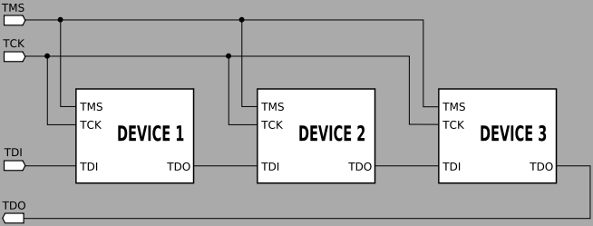
In principle, JTAG uses five signal lines. They form a chain starting at the debugger, where one device’s output is the next device’s input, until the result is returned back to the debugger.

- Test Data In (TDI) is the input from the debugger
- Test Data Out (TDO) is the return end of the chain
- Test Clock (TCK) clocks this data along synchronously, similarly to SPI
- Test Mode Select (TMS) lets the devices know that they’re being debugged — it’s a global chip select
- Test Reset (TRST) is an optional signal that resets all devices in the chain


