Adding Variometer Functionality To A GPS

Flying a glider, or similarly piloting a paraglider or hang glider, can all be pathways into aviation with a lower barrier of entry than powered flight. Sacrificing one’s engine does generate a few complexities, but can be rewarding as the pilot searches for various means of increasing altitude like ridge soaring or thermaling. You’ll need a special instrument called a variometer to know just how much altitude you’re gaining though, like this one which is built into commercially-available handheld GPS units.

These GPS units are normally intended for use on terra firma only, but [Oganisyan] has figured out a clever way to add this flight instrumentation to these units to help when operating a paraglider. An ATmega328 paired with a pressure sensor is added to the inside of the GPS units and communicates with an available serial interface within the units. To complete the modification, a patched firmware must be installed which adds the variometer function to the display. This upgrade is compatible with a handful of GPS units as well such as the BikePilot2+ or Falk Tiger.

For those who already own one of these GPS units, this could be a cost-effective way of obtaining a variometer, especially since commercially-available variometers tailored for this sort of application can cost around $200 to $500. It is an activity sensitive to cost, though, as it offers a much more affordable option for taking to the skies than any powered craft could, with an exception made for this powered paraglider which offers the ability for powered take off and flight extension using electric-powered props.

Thanks to [MartinO] for the tip!

Building A Swiss Army Lab With Software Defined Instrumentation

It’s a fair bet that anyone regularly reading Hackaday has a voltmeter within arm’s reach, and there’s a good chance an oscilloscope isn’t far behind. But beyond that, things get a little murky. We’re sure some of you have access to a proper lab full of high-end test gear, even if only during business hours, but most of us have to make do with the essentials due to cost and space constraints.

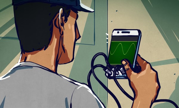
The ideal solution is a magical little box that could be whatever piece of instrumentation you needed at the time: some days it’s an oscilloscope, while others it’s a spectrum analyzer, or perhaps even a generic data logger. To simplify things the device wouldn’t have a physical display or controls of its own, instead, you could plug it into your computer and control it through software. This would not only make the unit smaller and cheaper, but allow for custom user interfaces to be created that precisely match what the user is trying to accomplish.

Wishful thinking? Not quite. As guest host Ben Nizette explained during the Software Defined Instrumentation Hack Chat, the dream of replacing a rack of test equipment with a cheap pocket-sized unit is much closer to reality than you may realize. While software defined instruments might not be suitable for all applications, the argument could be made that any capability the average student or hobbyist is likely to need or desire could be met by hardware that’s already on the market.

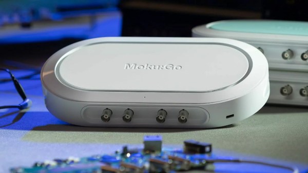
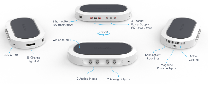
Ben is the Product Manager at Liquid Instruments, the company that produces the Moku line of multi-instruments. Specifically, he’s responsible for the Moku:Go, an entry-level device that’s specifically geared for the education and maker markets. The slim device doesn’t cost much more than a basic digital oscilloscope, but thanks to the magic of software defined instrumentation (SDi), it can stand in for eleven instruments — all more than performant enough for their target users.

So what’s the catch? As you might expect, that’s the first thing folks in the Chat wanted to know. According to Ben, the biggest drawback is that all of your instrumentation has to share the same analog front-end. To remain affordable, that means everything the unit can do is bound by the same fundamental “Speed Limit” — which on the Moku:Go is 30 MHz. Even on the company’s higher-end professional models, the maximum bandwidth is measured in hundreds of megahertz.

Additionally, SDI has traditionally been limited to the speed of the computer it was attached to. But the Moku hardware manages to sidestep this particular gotcha by running the software side of things on an internal FPGA. The downside is that some of the device’s functions, such as the data logger, can’t actually live stream the data to the connected computer. Users will have to wait until the measurements are complete before they  pull the results off, though Ben says there’s enough internal memory to store months worth of high-resolution data.

Of course, as soon as this community hears there’s an FPGA on board, they want to know if they can get their hands on it. To that end, Ben says the Moku:Go will be supported by their “Cloud Compile” service in June. Already available for the Moku:Pro, the browser-based application allows you to upload your HDL to the Liquid Instruments servers so it can be built and optimized. This gives power users complete access to the Moku hardware so they can build and deploy their own custom features and tools that precisely match their needs without a separate development kit. Understanding that obsolescence is always a problem with a cloud solution, Ben says they’re also working with Xilinx to allow users to do builds on their own computers while still implementing the proprietary “secret sauce” that makes it a Moku.

It’s hard not to get excited about the promise of software defined instrumentation, especially with companies like Liquid Instruments and Red Pitaya bringing the cost of the hardware down to the point where students and hackers can afford it. We’d like to thank Ben Nizette for taking the time to talk with the community about what he’s been working on, especially given the considerable time difference between the Hackaday Command Center and Liquid’s Australian headquarters. Anyone who’s willing to jump online and chat about FPGAs and phasemeters before the sun comes up is AOK in our book.


The Hack Chat is a weekly online chat session hosted by leading experts from all corners of the hardware hacking universe. It’s a great way for hackers connect in a fun and informal way, but if you can’t make it live, these overview posts as well as the transcripts posted to Hackaday.io make sure you don’t miss out.

How An Oscilloscope Probe Works, And Other Stories

The oscilloscope is probably the most versatile piece of test equipment you can have on your electronics bench, offering a multitude of possibilities for measuring timing, frequency and voltage as well as subtleties in your circuits revealed by the shape of the waveforms they produce.

On the front of a modern ‘scope is a BNC socket, into which you can feed your signal to be investigated. If however you simply hook up a co-axial BNC lead between source and ‘scope, you’ll immediately notice some problems. Your waveforms will be distorted. In the simplest terms your square waves will no longer be square.

Why is this? Crucial to the operation of an oscilloscope is a very high input impedance, to minimise current draw on the circuit it is investigating. Thus the first thing that you will find behind that BNC socket is a 1 megohm resistor to ground, or at least if not a physical resistor then other circuitry that presents its equivalent. This high resistance does its job of presenting a high impedance to the outside world, but comes with a penalty. Because of its high value, the effects of even a small external capacitance can be enough to create a surprisingly effective low or high pass filter, which in turn can distort the waveform you expect on the screen.

The answer to this problem is to be found in your oscilloscope probe. It might seem that the probe is simply a plug with a bit of wire to a rigid point with an earth clip, but in reality it contains a simple yet clever mitigation of the capacitance problem.

Continue reading “How An Oscilloscope Probe Works, And Other Stories”

Smartphone Bench Instrument Apps: Disappointment Or Delight?

If you are interested in electronics or engineering, you’ll have noticed a host of useful-sounding apps to help you in your design and build work. There are calculators, design aids, and somewhat intriguingly, apps that claim to offer an entire instrument on your phone. A few of them are produced to support external third-party USB instrument peripherals, but most of them claim to offer the functionality using just the hardware within the phone. Why buy an expensive oscilloscope, spectrum analyzer, or signal generator, when you can simply download one for free?

Those who celebrate Christmas somewhere with a British tradition are familiar with Christmas crackers and the oft-disappointing novelties they contain. Non-Brits are no doubt lost at this point… the crackers in question are a cardboard tube wrapped in shiny paper drawn tight over each end of it. The idea is that two people pull on the ends of the paper, and when it comes apart out drops a toy or novelty. It’s something like the prize in a Cracker Jack Box.

Engineering-oriented apps follow this cycle of hope and disappointment. But there are occasional exceptions. Let’s tour some of the good and the bad together, shall we?

Continue reading “Smartphone Bench Instrument Apps: Disappointment Or Delight?”

Analog To Digital Converter (ADC): A True Understanding

Back in the day where the microprocessor was our standard building block, we tended to concentrate on computation and processing of data and not so much on I/O. Simply put there were a lot of things we had to get working just so we could then read the state of an I/O port or a counter.

Nowadays the microcontroller has taken care of most of the system level needs with the luxury of built in RAM memory and the ability to upload our code. That leaves us able to concentrate on the major role of a microcontroller: to interpret something about the environment, make decisions, and often output the result to energize a motor, LED, or some other twiddly bits.

Often the usefulness of a small microcontroller project depends on being able to interpret external signals in the form of voltage or less often, current. For example the output of a photocell, or a temperature sensor may use an analog voltage to indicate brightness or the temperature. Enter the Analog to Digital Converter (ADC) with the ability to convert an external signal to a processor readable value.

Continue reading “Analog To Digital Converter (ADC): A True Understanding”