We so often hack for hacking’s sake, undertaking projects as a solitary pursuit simply for the challenge. So it’s nice to see hacking skills going to good use and helping someone out. Such was the case with this low-cost two-axis handheld camera gimbal intended to help a budding photographer with a motion disorder.
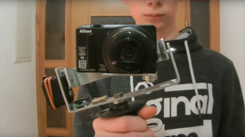
When [Tadej Strah] joined his school photography club, a fellow member who happens to have cerebral palsy needed help steadying cameras for clean shots. So rather than shell out a lot of money for a commercial gimbal, [Tadej] decided to build one for his friend. A few scraps of aluminum bar stock were bent into the gimbal frames and camera mount. Two hobby servos take care of the pitch and roll axes, controlled by an Arduino talking to an MPU-6050. Mounted to a handle from an angle grinder with the battery and electronics mounted below, the gimbal looks well-balanced and does a good job of keeping the camera level.
Hats off to [Tadej] for pitching in and solving a real world problem with his skills. We like to see people helping others directly, whether it’s building a gyroscopic spoon for Parkinson’s sufferers or vision enhancement for a nearly blind adventurer.
[via r/arduino]


That’s what I love about Hackaday, just people that go ahead and do things themselves. I don’t know how much time was spent on this, but this is not a trivial project.
This is indeed an advanced project, and I was initially skeptical about using RC servos, but wow, it works well! Well done OP!
RC servos probably don’t perform nearly as well as the brushless motors usually used for gimbals like this – but for this particular use case it appears they are “good enough” at a MUCH lower cost. A win for everyone. :)
If it’s for stills rather than video, and the exposure is fast enough, it’s probably fine.
nice, but without the instructions on how to do it, it is not so useful. In particular, I’d like to know what kind of PID parameters were used.
I am actually currently using open loop control, not PID. Arduino just simply reads the angles from the sensor and sends their opposite values to the servos. I have also tried PID control but as these servos have so much clearance between gears it did not work well.
Isn’t this still technically closed loop control by the very nature of using a servo? Servos have an internal feedback loop, hence why you can command them by angle so easily.
Technically it’s open loop control even though the servo itself is closed loop because the accelerometer is on the handle and not with the camera and this is still ‘bending’ my mind. I would have put the accelerometer with the camera.
It’s a great project, especially given that it’s was made as assistive technology for someone with cerebral palsy.
I thought the mirror test was a bit cheeky because a camera in a mirror becomes it’s own reference so the image taken will always be square to the camera.
Hi. Thanks for sharing my project ☺️
Gimbal is still in development – currently I am working on a model for 3D printing. I will make more detailed video once I finish it.
proper hacking! nice project…
A for effort but the performance needs improvement for sure (you can see the phone cam is much smoother in the video starting at 3:25). Ditch the RC servos.
All the TV networks should have this. YouTube does a good job on submitted shots.
https://youtu.be/L33ztTu-hKo
BTW, i also made a shorter version of this video with which I am applying to SciChallenge competition. Please like the video on YT al this will help me at competition.
Thanks☺️
Wrong link, sorry.
This is the right one:
https://youtu.be/_LXksfrvwEY