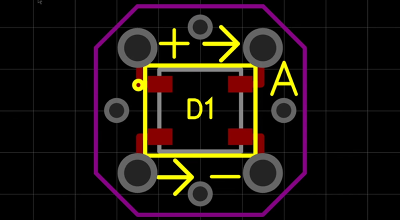
Just about anyone can make a simple LED cube. But what if you want to make a 1-meter cube using 512 LEDs? [Hari] wanted to do it, so he created two different kinds of LED boards using EasyEDA. There are 270 of each type of board, for a total of 540 (there are only 512 LEDs, so we guess he got some spares due to how the small boards panelized). The goal is to combine these boards to form a cube measuring over three feet on each side.
To simplify wiring, the boards are made to daisy chain like a cordwood module. However, to get things to line up, each column of LED boards have to rotate 90 degrees. You can see several videos about the project below.
We’ve covered EasyEDA before. It is a browser-based tool for defining PCBs and includes many other features like simulation and autorouting. You can download the CAM files from the tool or you can order the boards directly from the site very easily.
[Hari] apparently likes LED cubes large or small. EasyEDA, by the way, isn’t the only browser-based solution out there.


This guys demeanor and ideas are going to make him god status over time.
Hi SouperNerd!
I’m the nerd who’s working on the giant ping pong ball LED cube.
Your comment put a smile on my face. :-)
Thank you!
=Hari=
How do you make your videos? Can you share how you composite the video/audio? It’s so well done! Love it!
I second this! Hari’s videos are simultaneously concise, witty, and info-packed. And they look good too. My fear is that the answer to “how does he make them” is just plain hard work and attention to detail.
Still, Hari, if you ever want to do a “this is how I plan/shoot/edit/whatever my videos”, I’d watch it at least. :)
Lovebes & Elliot,
Believe it or not, all my videos are usually created using nothing more than a Samsung Galaxy S6 and iMovie.
I learned from many YouTubers such as Casey Neistat, that it’s not about the equipment, it’s about the story.
I always start a project that I’m excited about, then brainstorm on how to present it so the audience would share my excitement. I start with a bullet list outlining the content, shoot raw footage, edit to see how it feels, shoot more footage to keep the story going, edit, sometimes I have to reshoot to correct mistakes or explain things better, repeat until it doesn’t suck. :-)
I find it amusing how much time I spent editing. Obviously I must enjoy it because I typically spend a few hours in editing for each minute of video and until this last video, no one is paying me to do it. I suppose comments such as yours are my payment. So, thank you!!!
We need more of this attitude! Your videos are great.
There is no reason to make two PCBs. Just add solder bridges to allow alternate routing to each data pin and cut/bridge half the boards one way and the other half opposite.
…or just connect the data lines at a slight angle. No need for solder bridges. If the input and output pads are close to each other I bet it’s going to be unnoticeable.
Dang, those are great ideas! Where were you guys when I was brainstorming on how to solve this?! lol
Maybe next time :D
Thanks Alan! Thanks TacticalNinja!
=Hari=
Or have a “top” mounted ball and a “bottom” mounted and rotate the PCB 180 across the V+ and GND pins.
an extra few mouse clicks at design time vs an extra 25% soldering (5 instead of 4) at build time.
I’d choose the variant design.
But then again, I would also put a capacitor one each board (50% extra soldering!!). Maybe I’m doing it wrong.
I like his enthusiasm, ambition, the idea is great. But If he plans on using an arduino to drive the 512led cube then he’ll have to be really creative with his coding. Sheer memory requirements would be too great.
I’ve had a lot of success driving lots of WS2812s from a Raspberry Pi. So much more RAM and storage space means endless animation possibilities.
Many think it can’t be done reliably because of Linux timing, but that’s just not true. Check out jgarff on Github. Rpi_ws281x. Uses PWM peripheral over SPI. Works perfectly, no glitching.
I hope he goes down this path.
Hi Stu,
I was certainly one of those people who thought that a linux computer would be a bad choice for timing sensitive applications. Thanks for correcting my misconception. I’ll check it out!
Thx for the tip!
=Hari=
PS: If you have your project(s) documented online somewhere I’d love to check them out.
I don’t know what you are doing but 8x8x8x3 bytes fit just fine into a single atmega328p and since the leds themselves act as a framebuffer you can comfortably edit the whole array. A problem presents itself in that it takes over 15ms to update the leds if they are a single string. He can probably get a comfortable 20-30fps refresh rate, though.
If he used a Teensy 3.x he’d have heaps of space and computation power for a variety of things.
The newer WS2812!B! devices have a full bridge on the power inputs I believe, no need to arrange 5V to one side and 0V to the other. He could’ve gotten away with a single PCB rotated 180 every level.
Really?! I did not know that. That would really simplify things. Live and learn. :-(
Thx for the tip Dan!
Al,
Thanks for blogging about my project. Great job summarizing the project into just a few paragraphs! I thought my solution for daisy chaining the LEDs were innovative, but of course cordwood modules did that decades ago :-D
It really help my channel whenever Hackaday posts one of my videos.
Thanks again Al!
=Hari=
This is great. Always love a good Hari project (and associated videos!). Excellent application for Fadecandy!
Also worth mentioning Mike’s massive cube build — he took a different path but ended up with a terrific result: https://www.youtube.com/watch?v=O_RcTuE9fWc
You would not believe how much I drooled over my keyboard when I saw Mike’s cube. lol
But, I do not have the same level of expertise or monetary backing to do that. His is probably the most impressive cube I’ve ever seen. Thanks for sharing that link Zakqwy. Now I have to wipe drool my trackpad, again.
You can get individually addressable RGB LEDs in a 5mm through hole package. You could then build an old school LED matrix.
Wow – i did not know they exist, thanks for letting me know!