Integrated Circuit Reverse Engineering, 1970s Style

We are used to stories about reverse engineering integrated circuits, in these pages. Some fascinating exposés of classic chips have been produced by people such as the ever-hard-working [Ken Shirriff].

You might think that this practice would be something new, confined only to those interested in the workings of now-obsolete silicon. But the secrets of these chips were closely guarded commercial intelligence back in the day, and there was a small industry of experts whose living came from unlocking them.

Electron micrograph of a wire bond to the Z80 CTC die

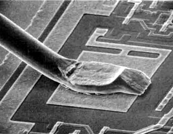
Integrated Circuit Engineering Corporation were a Scottsdale, Arizona based company who specialised in semiconductor industry data. They have long since been swallowed up in a series of corporate takeovers, but we have a fascinating window into their activities because their archive is preserved by the Smithsonian Institution. They reverse engineered integrated circuits to produce reports containing detailed information about their mechanical properties as well as their operation, and just such a report is our subject today. Their 1979 examination of the Zilog Z80 CTC (PDF) starts with an examination of the package, in this case the more expensive ceramic variant, then looks in detail at the internal construction of the die itself, and its bonding wires. We are then taken in its typewritten pages through an extensive analysis of the circuitry on the die, with gate-level circuits to explain the operation of each part.

The detail contained in this report is extraordinary, it is clear that a huge amount of work went into its production and it would have been of huge value to certain of Zilog’s customers and competitors. At the time this would have been extremely commercially sensitive information, even if it now seems like a historical curiosity.

The Z80 CTC is a 4-channel counter/timer peripheral chip for the wildly succesful Z80 8-bit microprocessor, in a 28-pin dual-in-line package. We were surprised to find from a quick search that you can still buy this chip from some of the usual suppliers rather than the surplus houses, so it may even still be in production.

If IC reverse engineering takes your fancy, take a look at our archive of [Ken Shirriff] posts.

Thanks [fortytwo] for the tip.

540 PCBs Make A Giant LED Cube

Just about anyone can make a simple LED cube. But what if you want to make a 1-meter cube using 512 LEDs? [Hari] wanted to do it, so he created two different kinds of LED boards using EasyEDA. There are 270  of each type of board, for a total of 540 (there are only 512 LEDs, so we guess he got some spares due to how the small boards panelized). The goal is to combine these boards to form a cube measuring over three feet on each side.

To simplify wiring, the boards are made to daisy chain like a cordwood module. However, to get things to line up, each column of LED boards have to rotate 90 degrees. You can see several videos about the project below.

Continue reading “540 PCBs Make A Giant LED Cube”

USB Charger Fooled Into Variable Voltage Source

USB chargers are everywhere and it is the responsibility of every hacker to use this commonly available device to its peak potential. [Septillion] and [Hugatry] have come up with a hack to manipulate a USB charger into becoming a variable voltage source. Their project QC2Control works with chargers that employ Quick Charge 2.0 technology which includes wall warts as well as power banks.

Qualcomm’s Quick Charge is designed to deliver up to 24 watts over a micro USB connector so as to reduce the charging time of compatible devices. It requires both the charger as well as the end device to have compatible power management chips so that they may negotiate voltage limiting cycles.

In their project, [Septillion] and [Hugatry] use a 3.3 V Arduino Pro Mini to talk to the charger in question through a small circuit consisting of a few resistors and diodes. The QC2.0 device outputs voltages of 5 V, 9 V and 12 V when it sees predefined voltage levels transmitted over the D+ and D- lines, set by Arduino and voltage dividers. The code provides function calls to simplify the control of the power supply. The video below shows the hack in action.

Quick Charge has been around for a while and you can dig into the details of the inner workings as well as the design of a compatible power supply from reference designs for the TPS61088 (PDF). The patent (PDF) for the Quick Charge technology has a lot more detail for the curious.

Similar techniques have been used in the past and will prove useful for someone looking for a configurable power supply on the move. This is one for the MacGyver fans.

Continue reading “USB Charger Fooled Into Variable Voltage Source”

Game Boy Mod Uses Raspberry Pi Compute Module 3

[inches] wanted the power of a Raspberry Pi 3 in a form factor closer to the Pi Zero for a Game Boy mod. This led him to design a custom PCB to interface with one of the less popular items in the Raspberry Pi line: the Compute Module 3. A hardware comparison between the three platforms is available here.

After correcting some minor issues, it booted correctly on the first try. The final result is slightly larger than a Raspberry Pi Zero, but significantly smaller than the Raspberry Pi 3, and fits perfectly inside the Game Boy for a clean build.

The Raspberry Pi Zero remains difficult to source in some parts of the world and can cost nearly as much as the more powerful CM3 (e.g. in Southeast Asia). If you’re comfortable making a breakout board and benefit from the added computing power, it’s a reasonable option when it needs to be small.

Worth noting is that the Raspberry Pi Foundation does sell an open-source development kit for the CM3 that has been used in some projects, but the retail cost is relatively high compared to a Raspberry Pi 3. Smaller but less feature-rich breakout boards like the one by [inches] make the CM3 more accessible.

Thanks to [Lou Hannoe] for the tip.

Hackaday Prize Entry: Refugee Reuniter

The world is dealing with a serious refugee crisis, and with that comes a problem: finding people. The Refugee Reuniter, a project entered into this year’s Hackaday Prize, is a possible solution to this problem. It’s a device that allows people to reconnect with their family, whether it’s children lost in transit to destination countries, or mothers and fathers reuniting.

The basic problem the Refugee Reuniter is trying to solve is tracking people. This is a whole ball of wax that involves privacy and technological concerns. Ideas put forward so far include GPS trackers, implantable RFID tags, and other such draconian measures. The Refugee Reuniter puts another spin on this, while still assigning a unique, electronic ID to every name.

The basic hardware for the Refugee Reuniter is simply an RFID wristband or token, carried with the refugee at all times. This token is mapped to a name that can be looked up in a small terminal, tied to a specific location. If a refugee logs into one of these terminals, their location is logged and they can search for their relatives. It’s a simple technological solution to what is basically a gigantic dead-tree logbook, only backed up into an online database.

First Thoughts On The New UP Core

I normally stay away from talking about x86 single-board computers because I don’t have a lot to say about them. They’re too expensive, and run too hot, to be interesting. Enter the new UP Core funding now on Kickstarter.

The UP Core is just 56.5 mm × 66 mm (2.2 in × 2.6 in) and powered by a 64-bit Quad Core Intel Atom clocked at either 1.44 GHz or 1.92 GHz. It will ship with either 2 GB or 4 GB of RAM, and either 32 GB or 64 GB of eMMC. The board has a USB 3 port, HDMI, DSI/eDP, and two MIPI-CSI ports supporting either a 2 MP or 8 MP camera. It has both WiFi 802.11 b/g/n and Bluetooth LE built-in.

In other words it’s powerful enough to serve as a desktop PC running Linux, Android, or a full Windows 10 installation. The cheapest UP Core configuration—with 1 GB memory and 16 GB eMMC—is €69, or around $75. Continue reading “First Thoughts On The New UP Core”

The Trouble With Old Model Steam Engines

Model steam engines have intrigued hackers and makers for over 100 years. Many of us have seen old steam engine models up for sale at garage sales and various internet auction sites. The problem with these engines is the fact that many of them were sold as rough casting kits. This means the quality of the model is only as good as the original owner’s machining and fabrication skills.

[Keith Appleton] is something of a steam engine expert. In this pair of videos, he takes us through troubleshooting two engines. Keith goes on to show some of the common failures he’s found while working on these wonderous little machines.

First off is the paint. If you find nuts, bolts and random parts painted in different colors, the engine is probably bad. It sounds strange, but [Keith] has found this to be a rule over his years of working with these engines.

Another problem is rattles. [Keith] found one of these engines rattled terribly. The culprit was the crankshaft. Not only was it the wrong size, but it was built wrong. These engines use built up crankshafts, rather than shafts machined from a single piece of metal. This engine’s crankshaft was threaded into the crank webs rather than pinned. Whoever built it tried to re-engineer the design of the crankshaft, and failed miserably.

You can check [Keith’s] videos out after the break. Want more displacement? We’ve covered the simplest steam engine, and an insanely detailed steampunk battleship, which of course is powered by steam.

Continue reading “The Trouble With Old Model Steam Engines”