How creative are you when you make your circuit boards? Do you hunt around for different materials to use for the board? As long as it’s an insulator and can handle the heat of a soldering iron, then anything’s fair game. Or do you use a board at all? Let’s explore some options, both old favorites and some you may not have seen before, and see if we can get our creative juices flowing.
Transparent Circuit Boards


Let’s start with the desire to show more circuit and less board. For that we can start with [CNLohr]’s circuits on glass, usually microscope slides. What’s especially nice about his is that he provides detailed videos of the whole process, including all the failed things he tried along the way. Since he didn’t start with copper clad board, he instead glued his copper sheet to the glass using Loctite 3301. That was followed by the usual etching process, though with plenty of gotchas along the way.
In the end, he made a number of circuits, including an LED clock with the LEDs on the glass itself, and even attempted leading the community in making a glass keytar. The latter didn’t work out, but the resulting glass circuits are a work of art anyway.
What about making a transparent circuit board out of acrylic? [Frank Zhao] attempted just that by laser cutting troughs into the acrylic for the traces, and then drawing in nickel ink. But something in the ink ate into the acrylic, and as if that wasn’t bad enough, the voltage drop across the nickel was too high for his circuit. Suggestions were made in the comments for how to solve these problems, but unless we missed it, we haven’t seen another attempt yet.
But we’ve only just begun. What if you wanted even more transparency?
Circuit Boards In Air
One way to get more transparent than glass or acrylic is to do away with the board altogether. Historically this is called point-to-point construction, a term which predates printed circuit boards. The name for it we see more often here on Hackaday is a Dead Bug circuit, a name that comes from the appearance you get when you install a component upside down and solder to its legs.


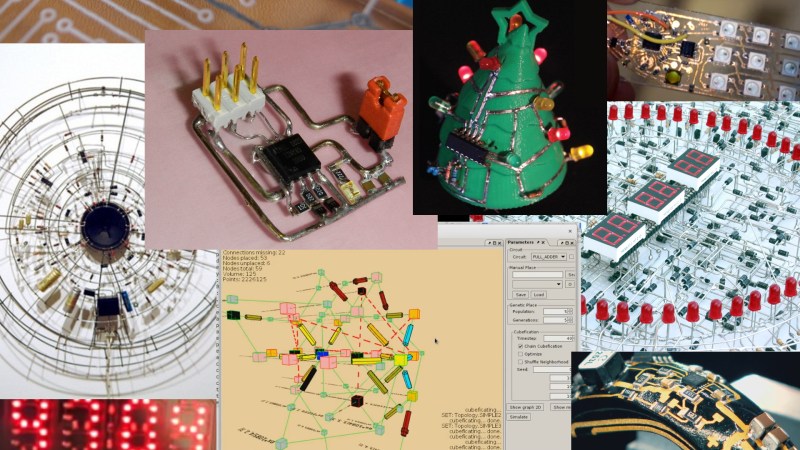
[matseng] was bored one afternoon and made a Dead Bug version of the Little Wire circuit, an AVR programmer with a minimal parts count. After an hour or two using a fine tipped soldering iron, 0.4 mm solder and a stereo microscope he came up with the very elegant wire and parts only circuit shown here. The dead bug is the SOIC version of an ATtiny85.
However, these types of circuit don’t all look like dead bugs. Some far from it. Among the most spectacular has to be [Gislain Benoit]’s circular digital clock made up of thousands of components that keeps time using the North American 60 Hz mains voltage cycle.


Surprisingly not represented here on Hackaday, perhaps we missed it back around 2009, is the boardless artistic circuitry of [Peter Vogel]. These actually work too. Some monitor light levels and respond with
changing sounds, some light up, and some have rotating propellers.
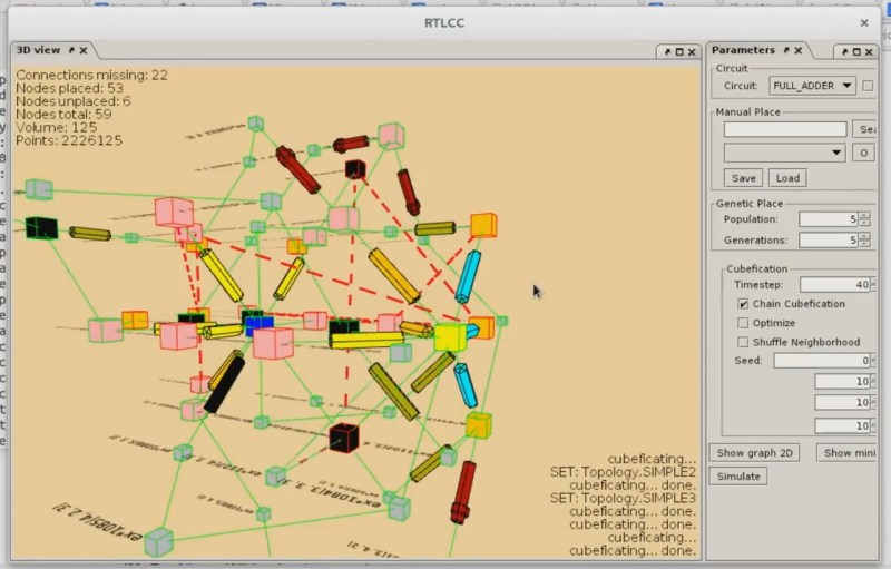
[Anderson] has done a lot of work towards taking dead bugging to the next level, referring to these as volumetric circuits. He’s written software, called Pyrite, for designing them. It lets you draw the normal 2D version, then test it in a simulator, and then it folds the circuit into a 3D version for you to use as a guide. He’s also done some R&D into 3D connectors for prototyping.
Encapsulated Dead Bug Circuit
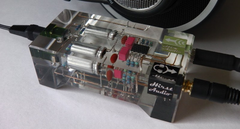
Then there’s the combination of transparent board and Dead Bug circuit. A perfect example of that is [Rupert Hirst]’s beautiful headphone amplifier circuit encapsulated in crystal clear resin. If you’ve worked with casting this much resin at once then you’ll know that it can potentially reach high temperatures as the resin cures. In this case temperatures reached a nail-biting 108°C while the capacitors were rated for 125°C. There was also the danger of resin leaking into the jack cases. To prevent that, [Rupert] first hardened a little resin around wherever leaks could occur. The result was a functioning amp and a work of art.
Circuits On 3D Surfaces


Next up is putting your circuit on boards that are far from board-shaped. [FESTO]’s bionicANTs ant army is one such example. The boards are 3D printed ant bodies. The circuit is applied using 3D MID, a process where the body is printed in a special non-conductive material onto which a laser draws out the traces. That’s followed by dipping the body in various baths to apply copper, nickel and gold layers.
The only other example our searches turned up of circuits involving mostly basic components being applied to 3D printed objects was a research project called SurfCuit. This one included software similar to the one [Anderson] worked on for Dead Bug circuits. The software allows you to drape a 2D circuit onto a 3D model. It then adds channels and holes to the model as needed. Once 3D printed, you then apply the actual wires and components to those channels and holes.
As we said, we had trouble finding these. If you’re aware of any more circuits on 3D printed objects, please share them in the comments below.
Circuits On Clothes


That brings us to circuits on clothing. In this case the wiring is often conductive thread, woven into the cloth itself. Of course it’s faster to do this by machine and we’ve seen a version of this from Cynthia Design Studio that lays down the three parallel traces you need to run WS2812 LEDs.
Conductive thread used in fabrics then connects components sewn onto the cloth. Most often this technique is used to add LEDs, as [Martijn] did with his climbing jacket. There, the LEDs change color based on the altitude as determined by a barometric sensor and other components. But there are other uses too. One such is [Afrdt]’s EMF wave detecting dress that plays back the signals using a vibrating motor, and as sound to earbuds that can be plugged into a collar.
Closing The Circuit
In this article we’ve been highlighting the artistic, the creative, and even the jaw droppingly beautiful. But this sort of circuitry can go the other way too, as our [Dan Maloney] points out in his article about getting ugly with circuits.
In any case, hopefully that’s gotten your creative juices flowing for your next circuit. Naturally we couldn’t fit every sample of awesomeness into one article, so let us know of any others that you particularly fancy, or better yet, that you’ve made yourself!


Nice “Out of the Box” ideas!
I especially like the headphone amp potted in acrylic, and the cone shaped circuit on the “Christmas Tree”.
I like the circuits on 3d surfaces the most as it makes use of an otherwise wasted surface. However, the circuit has to be added to the object. Perhaps in the future, there can be something like SLS that can build the circuit inside the object as well as place the components while it’s built. The end result would be a circuit inside of a 3d printed object! :)
Then make it yourself, patent it. That’s a really good idea. Make you rich. And do it fast before people like me steal your idea. I’m not an idea theif. But if you wait to long I’ll build my own prototypes
Humble FDMs can pause, pick an place the circuit board inside and print the remain of the encosure.
My early circuits were literally built on a ‘breadboard’ – a scrap piece of 1/4″ plywood, with finishing nails hammered into it, and the components soldered onto the nail heads used as tie points..
That’s more or less where the term “breadboard” came from. The very early circuits were literally build on a kitchen breadboard (or any substitute) with component leads spread out and screws (and washers) used as the connecting points.
I remember my first board. I was about 9 or 10. I’d use cardboard. I’d poke the leads through the cardboard. things like transistors would have to be pre-bent. Then I would take old transformers and unwrap the coils. I would then take that wire and wrap it around the leads on the other side. Pull slight tension and wrap it to the other connection. Completely solderless. These boards of mine would get engulfed in fire real easy. Saved up and bought my first soldering iron around 12-13. But it was somthin. Good times, used to have so much fun figuring the stuff out.
You forgot a sub genre of the dead bug circuit, Manhattan style.
Dan already did a full article on Manhattan style so I just referred to that https://hackaday.com/2016/05/04/getting-ugly-dead-bugs-and-going-to-manhattan/. The reference is at the end but I guess I could have put it in the dead bug section too.
Yeah – I’m a fan of Manhattan-style too, especially for RF circuits, and you build them on an un-etched copper-clad board as a ground plane, and scribing islands, or glueing on bits of cut-up circuitboard to make connection points. Works very well, and can be reworked if necessary.
Anyone else here remember adding RAM to computers by stacking ICs? Separate wires for the CS (chip select), the rest soldered together.
http://www.minuszerodegrees.net/5150/early/5150_early_64kb_memory_expansion_4132.jpg
http://quinndunki.com/blondihacks/wp-content/uploads/2013/06/IMG_2130.jpg
I tried to make a logic unit for a computer as a kid by stacking up 7400, 7432, 7408, and 7486 ICs and using VCC as chip select. It actually worked if I recall.
Nand, Or, And, Xor
Love it.
I did that ages ago… Had a stack of a RAM chips. Every pin was soldered together, except the data bus pins (a different chip for each wire of the data bus)
Yup, I used to mod Atari ST’s that way all the time!
Some RAM mfrs made 2 versions of the chip (CS & /CS), so ALL the pins could be paralleled.
BTW, I bet the pictured chips are 64kb fallouts, labelled as 32k.
My first big RAM card (32kB) used 16kb fallout chips (hence, 8kb). The ICs were marked as to which half was good, and each of the 4 banks on the card had to have all the same kind of chip installed (and a jumper set appropriately).
Dude… Those PCBs on 3D surfaces! I never saw that! It is seriously cool and makes me wish I could figure out an easier way to do it at home! Also, you missed the 3rd type of transparent PCBs, where they use copper tape to lay down tracks. I love canvasing articles like this!
Now for a 3d retrocomputer!
Been working on this.. 1.5mm Acrylic, kapton tape, copper tape. Spraypaint. Laser etch off paint. Chemically etch off copper.. Back in laser cutter to cut holes and shape.. Solder..
https://lh3.googleusercontent.com/frpULAC_fhFR1nSww3FNZIN-fc89pQhqDn1A2ItzkQNuhSCa30HipnlLwqeI3pShr1ZsXIHnMRgpEWw1b-2ZkY8l4Wdsd8SVjPOfnqGHSxfMUyDTpOQazc-RKQyDEKsH16LuTTu6i12F0cJhJjCFhUoTT3zVjvkoDsx4lOaN-2TqjSzAPZsD3uGFidQ1Udrej2fqoo73zZyHGLeb1HrDkczIaKLYbUkpX8MmORKB3OpjLscJuErSDXRzRyfGYcFesaU7vHyBrs7JZZlQQUaWYilWOMpu8rh2N6EWYgX41yfBJIhfmrySxhIJcc_1FLm1vr5WqEYHCkV1NwQ4VtvhUHwm6ZFwzZKtgktPulPeHz2RVakwFODrmixFLHxlXspMdZtY2wleOp7-vAYcUuxfFTrpkLQW9jgzHcLIX2hHSlxs4TBQK9FvOvrfT6LBw3vVnn-xPg-ck0BTkIbAI2loQFwu60rxXh9P28ikWBit6LkvXz6GwnuF4RGTX5Z2cB0r8FIET7L1SBxw_D3UJXhoPopcX4RtJKPSqn5qgxn84vbR5PL9wWfMIceg3myto3wUkRjUtPkyTLJIF-ZurVTxLtHhP1hrNrft3ADthwa4d78rhz3resJDfgGa0WB3PEdux7U6MhU-ObYFbXyqQWAfGs52TDSVWdsH_bRlzT3m8e_tm4w=w1188-h891-no
https://lh3.googleusercontent.com/pu-otrN-URyFntXiAo94hlVmO0W4h-wg860etpCoYAt3xmXnqmqmUD-mDS6SLRfW8ONCNxsU6w0NnyyDaJBM0psKqYISG81GH0b-SO2-ZSJqQ1yWc45HUx0PvzrEl3tIfw_OPc0A9qfRb2kA0bTdHZDMYWwYh7bDzDThDTlqXTeesLUAF1ZF_SfuAIh8VkGIpdQPhlE4JRFT6NHRJg7CQ3iPTpHDfMrehXJ0ubDNb5jYbrBLITP3q1qGH28GqhIuGLKaNFUMeydfenLg30HBVMsOMTpCuUxx3b_mR14GUgfejhWn5K9kUUjxTxcrRRcIjSOXUAHb_4h8F7GN9UB–4gEm8A3PABrj3CeCH851ibnYvrvHceYsnZNB6i-nDO6E5g5rOJ22vMdv5qcIjCj5eqj5yFtaavmY6Bp9IgbXjnQ58w3A3CFsWmLIStGDCw6aZeEvxD6rjWKMZ4uln79hx6AVRzO5lXQ8PDrhzSVuK2ft4ozriqBwhGhNYXaf8zlKoUIn8MfR-lEN_CJ0aO5EORnUBFEvP00Lzx-baFBr01szLquypeUp4hb_3dgPboUrXhuD0nUoLmtQdiXQDRT2LpAss3KesXfvbPM4miZUsQCK-Q8bKraGHC2eC5zIpM1YS3R5nQTrXpaRtmhZzDadxg3RM0jIQMXobA1SyuNzfHWFUE=w1188-h891-no
I was expecting them to embed the images.. Maybe I did it wrong?
With a URL like that … I was expecting it to turn off the universe.
Wouldn’t that “air build” acrylic encapsulated audio circuit catch a lot of hum AC noise?
No more so than any project in a plastic box. I’ve built and seen built a LOT of audio circuits in plastic project boxes with no shielding that didn’t pick up appreciable hum. If the sensitive inputs are protected by surrounding circuitry, it is a bit self-shielding.
If it is something that takes line level signals, the noise has to be pretty bad to be picked up.
http://mikelow.net/notebook/pics/crt_resin_03.jpg
It says the CRT still works but I don’t think the project ever got finished http://mikelow.net/notebook/1_boxes.php
I think a wonderful collection of such devices can be found at http://www.jackdollhausen.com/shebang/works/1amaster.htm with some notes about how he does it at http://www.jackdollhausen.com/shebang/quest/howto/how.htm.
I found him when working on some PICs . I was looking for bootloaders and found his at http://www.jackdollhausen.com/shebang/jmon/index.htm . When i realized he called it a “monitor”, like the old cpm control programs were called i knew it was the one i wanted. Has worked like a charm too!
Nice!
I love the circuits created on 3d surfaces!
https://www.youtube.com/watch?v=eBxeVaDqe4g
Oh, cheers mate. That looks good!
That’s nice!
I wonder if it’s possible to use the CD layer as a ground plane instead of removing it.
This one is also fun, Tortilla Breadboard:
http://www.seattlerobotics.org/encoder/apr98/breadbrd.html
:o)
Soimeone should make a complete 8088 this way, with ICs and LEDs galore!
These are some awesome builds. Great to have them all in one place.
I’d swear I’ve stuck some [Peter Voegel] stuff in HaD somewhere, but I could be wrong. He’s an awesome artist.
Hmm… electroplating circuits on top of 3D models. Breaking out the chemistry set.
My search was for ‘vogel’ but I just tried ‘voegel’ and anything ‘peter vo’ by you and turned up nil. I was surprised that we hadn’t mentioned him before.
I just searched for ‘peter’, is this one of his? https://hackaday.com/2014/10/15/peter-and-the-amazing-technicolor-phone-wire-bracelet/
Nope, that’s Peter Brown, wood worker and resin caster extraordinaire.
Some of the resin castings I’ve seen on HaD, including the telephone wire ring have inspired me to try it as well. I’m planning a little project to embed some electronics in resin to make a bangle, I’m not sure what to do about a battery compartment or recharging an embedded battery as I’d like it to be waterproof, it’s a work in progress.
I don’t know why I tossed an “e” in there — the dude’s name is spelled right at you spelled it. (Duh!)
And yeah, it looks like we’ve never covered him. Dang…
http://vogelexhibition.weebly.com/
http://www.bitforms.com/artists/vogel
http://www.petervogel-objekte.de/
Wow, that is some beautiful work. Thanks for the links.
No ‘Alligator-clip’ circuit here?