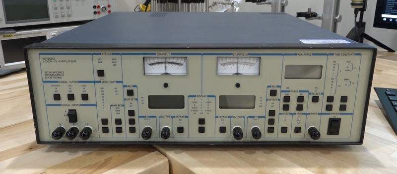
If you have about an hour to kill, you might want to check out [Shahriar’s] video about the Stanford Research SR530 lock in amplifier (see below). If you know what a lock in amplifier is, it is still a pretty interesting video and if you don’t know, then it really is a must see.
Most of the time, you think of an amplifier as just a circuit that makes a small signal bigger in some way — that is, increase the voltage or increase the current. But there are whole classes of amplifiers designed to reject noise and the lock in amplifier is one of them. [Shahriar’s] video discusses the math theory behind the amplifier, shows the guts, and demonstrates a few experiments (including measuring the speed of sound), as well.
The math behind the amplifier is mostly trig, although there is a little calculus involved. The idea is to mix a reference frequency together with the signal of interest. This will result in the sum and difference of the two signals. Integrating the signals will — over time — zero out.
That may not be intuitive, but consider this: thanks to Fourier analysis, we know that any signal can be decomposed into a bunch of sine waves. Since a sine wave has equal positive and negative excursions, the area under it is zero if you integrate over an entire period. If your calculus is rusty, integration is more or less adding up infinitely thin slices of the curve which gives the area under the curve. Since the sine wave has equal positive and negative areas, the area underneath is zero.
An amplifier that zeros out the input isn’t very useful. However, there is a catch. If the reference signal and the input signal are out of phase but equal in frequency, then the difference term will be a constant that doesn’t vary with time. When you integrate the entire signal, that constant will stick out like a sore thumb.
That’s the basic idea. If you want more details, the video does a nice job of explaining it as well as showing it in practice.
If you notice in the SR530’s block diagram, there are many PLLs, a topic we’ve covered before. You might wonder why you can’t just filter the frequency of interest. In theory, you could. But as [Shahriar] explains, to get the same performance out of a filter would require an impractically narrow filter.


“The math behind the amplifier is mostly trig, although there is a little calculus involved.”
Hold on. *takes swig of beer* Continue.
Once the math started… Take a sip of this hop double IPA. OK.
His videos are always really interesting.
[disclaimer type=”shameless_self_advertisement”] Pixels in consumer-grade time-of-flight range imagers like the Kinect v2 are basically little photonic lock-in amplifiers. Turns out you can use this property to do all sorts of non-depth-related fun stuff in a single shot. Here’s our upcoming research paper about it:
https://light.cs.uni-bonn.de/snapshot-difference-imaging-using-time-of-flight-sensors/
[/disclaimer]
very interesting!
Very interesting!
Have you experimented with using a microphone to control the sensor? I’d be curious if that could be used to selectively amplify parts of an image that oscillate and contribute to audible noise. By filtering the microphone signal, you could select various frequency ranges, and for example visually identify resonances.
Certainly not impossible, except we’re using modulation frequencies in the lower MHz range, for which these sensors are laid out. The integration time (typ. 1ms) limits the range of modulation frequencies; can’t squeeze too many audio oscillations into that short amount of time…
Someone asked earlier what they could use their FPGA for. This would be one of them.
Thats a very nice paper, I have read it before.
Do you know how to contact whom @ microsoft for keeping a Kinect V2 at the highest modulation frequency setting (without simply discarding the lower modulation frequency frames)?
The official kinect forums have multiple posts asking how to do this, with only non-responses or a specific microsoft contact address without response.
Yet there are multiple papers of researchers where the researchers describe receiving custom firmware from microsoft to achieve this?
Your video starts by mentioning the kinect, but then continues with a different depth camera from TI…
greetings
Your site is down :(
I remember some of the theory from my graduation time. It sounded like black magic to me then and sounds the same today!
Thanks for the article.
fourier (frequency) analysis does use the sine function but is not trig. it is usually considered calculus.
Actually, it’s quite common to look at these types of measurement in terms of phasors. Before you know it, you’ll find yourself forming parallelograms out of vectors in the complex plane. Boom — trigonometry :)
Even more common is to add and subtract numbers. Even sooner than you realize, BOOM – algebra! o.0
Not sure if that’s the point though.
For low frecuency 5000Hz lock in and sine generator IC ne5521
From a signal processing / RF point of view, this is “just” modulating a signal, demodulating it, and using an extremely low frequency lowpass (to effectively get an extremely good bandpass of the modulated signal)
And yet all sorts of really cool things come out of it.
It is also akin to a direct conversion or homodyne receiver.
Several things don’t “add” up (pun intended). For the nontechnical (and audio engineers), “mix” may mean “add”, but for electrical engineers, “mix” is the multiplication of two signal into a product. It is the product of two DIFFERENT frequency sines that produces their sum and difference frequencies. The “product” of ANY two “signals” (single frequency sines here) in the time domain is the convolution of the their Fourier coefficients in the frequency domain. Mixing in reality is a nonlinear process because it produces frequencies other than the original frequencies (that would be the sum of the two frequencies) — that is the “definition” of nonlinear: it doesn’t comply with superposition. A tacit assumption is that there is no limiting or clipping, as that also produces harmonics plus the sum and differences of those harmonics too as limiting tends to mix (i.e. multiply) the signals.
Note that your observation that mixing of two sine wave results in a DC offset wrong. It doesn’t if the mixing is “linear” (in this sense, since the multiplication is itself nonlinear, what I am inferring is that there is no internal limiting/clipping in the multiplier). Find your trig book and look up product of sines. You will find that formula: sin(a) * sin(b) = 1/2( cos(a-b) + cos(a+b) ). As you can tell, there is no DC term! That only happens due to problems in the mixer.
The Fourier expansion of a square wave shows that it is the SUM of a series of odd harmonics. In fact, the fundamental’s peak-to-peak is about 30% LARGER than the original square wave’s peak-to-peak. [OCD moment: I recall a group of young software and hardware engineers scratching their heads as to “why does the fixed point arithmetic of this ADC measured square wave have an arithmetic overflow?” They maxed the gain for the square wave so the signal was just under the ADC’s range, but when they calculated the amplitude of the fundamental, bam, arithmetic overflow. I was assigned the issue and found the “problem”. Reducing the gain on the square wave made everything work fine.]
[OCD kicking in again: I also recall building a graphic equalizer kit for a friend while I was in college. Shortly after he took it home I got a call from him: “It keeps blowing my speaker overload breaker!” he said. I went over with my oscope and we played around with “normal” rock music. Everything was fine. I asked: “what did you do to get it to blow?”. He said, all I did was this and he raised the highest two frequency bands to max, but it went out before that. He raised the turntable’s tonearm. I remarked that I didn’t hear anything other than some more treble until the breaker kicked in again. I scoped it where is was, but now there was a large twenty-something KHz signal that was at nearly the full volume coming out (remember, the music was off!). We lowered those band settings to normal and saw that waveform diminish in amplitude and then disappear. Huh? I called the kit manufacturer the next day and he said: “Yeah. We saw that too. We’ll send you a set of replacement op amps right away that will fix that. The manufacturer said that that batch of op amps aren’t fully unity gain stable.” Good thing they socketed the op amps! ]
Ironically, even a slow op amp can cause harmonic distortion (i.e. nonlinear operation) due to its slew rate being too small for the signal’s amplitude needs. It’s not the same kind of distortion as limiting/clipping and the harmonics it generated are even harmonics since it tends to make a sine wave look more like a triangular wave!
[ OK. OCD in check now. Thanks! ]
There is a DC offset if you mix *twice*, and this is what the lock-in amp is for.
It does the second ‘mixing’, *after* you use a nice high-Q low-noise amp tuned to about the band of the image that your intermediary signal is at. (which is where all the advantage lies).
To use the lock-in amplification technique, what you want to do is set up the *first* mixing to be somewhere within your experiment.
Consider using a full-bridge strain gauge — it is multiplying your excitation source by your ‘signal’ (the strain), even if it has a lousy ‘gain’. So you just excite it with the same AC source that you feed to the reference input of the lock-in amp.
The lock-in amp then accepts this tiny weak signal from the sense outputs of the bridge (in a narrow band, due to it being an image near the reference frequency) and amplifies the crap out of it, before mixing it back down to ‘DC’. The final low pass filter of that rejects any and all other images.
The reason the technique works so very, very well, is because one can fairly easily construct the low-noise amplifier to have very low noise in some narrow band away from DC, whereas an amplifier (say a really low-noise, instrumentation amplifier) that tries to do so will always be fighting against 1/f noise (aka flicker noise, aka the consequence of having an un-nulled drifting offset voltage… such as what a transistor does when its temperature (or even age) changes).
There’s a bunch of mucking around in making sure you don’t end up with a null due to having an unfortunate phase shift, which the cos/sin quadrature detector solves for you. (particularly where the thing will get you a nice filtered phase/magnitude output). Without such nice gear as this, you also have to tune the LNA’s passband so it is in the right range for the frequency of the reference that you’ve used.
I’ve seen a bunch of different amateur designs for doing lock-in amplification half-right on the web. They seem to usually forget the tuned-band LNA between whatever is ‘detecting’ the signal, and the heterodyning mixer. There are also plenty of designs that do it without seeming to realise what they’re doing, such as AC bridge excitation systems that foolishly omit the bandpass part of the LNA design, and gain at least good offset rejection, at the expense of having almost-as-complicated a system with a tiny fraction of the SNR they could have had, due to still doing the amplification at about DC.
Come to think of it, switched-capacitor filters are more or less the same sort of thing, just replacing the constant-sine reference with a square wave, and are effectively non-quantised (analog value, discrete-time) time-sampling systems. They usually give only about ‘8 effective-bit’ signal quality though.
Direct downconversion is the same thing again, really, once you realise that a sampling ADC is really multiplying the signal with a sequence of impulse responses, in addition to quantising it to digital.