[Big Clive] had some 22mm digital AC voltmeters, made to put in a panel. There was a time when this would have been a significant pain, since it required you to make a large square hole. Of course, in a world of CNC and 3D printers that isn’t as big a deal as it used to be, but the ones [Clive] has are nice because having a round footprint you can drill a hole for them with a hole saw or a stepped bit. Of course, he wasn’t satisfied to just use these inexpensive meters. He had to tear one apart to look inside. You can see his review and teardown in the video below. The meters are available in a range of AC voltages, although [Clive] didn’t think the ones he had would safely handle their rated maximum.
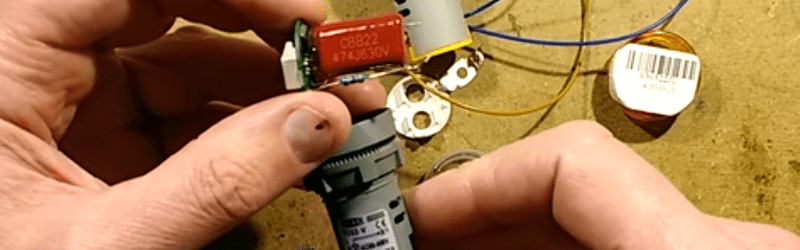
Inside, the modules reminded us of cordwood construction in a way. Most of the electronics are on a small round board. But several components connect to the board and the bottom cap in a vertical orientation. The meters are available in several colors, but [Clive] likes the red ones as they appear brighter than the others. The voltage reading compared favorably to a Fluke meter.
The verdict is that for the price (under $2 from China; a little more in the US) they are handy, but you might not want to consider running significant voltage through them. You could use these instead of pilot lights and get the voltage reading for free. We were surprised that someone doesn’t make a DC version in the same form factor, at least if they do, we couldn’t find it. If you don’t mind drilling the square hole and letting a bezel cover your sins, you could use a universal meter with an Arduino instead for many applications.


Read the rest of the sentence…
That is the end of the sentence and the author wrote “a large square hole”.
“…but the ones [Clive] has are nice because having a round footprint you can drill a hole for them with a hole saw or a stepped bit.”
I meant “paragraph”, sorry I didn’t point out the obvious in a more obvious fashion.
That was about using an alternative
“[Big Clive] had some 22mm digital AC voltmeters, made to put in a panel. There was a time when this would have been a significant pain, since it required you to make a large square hole.”
Except it doesn’t mention any alternative, the photo and video both show 22mm round hole parts and that is what they are working with here?
“If you don’t mind drilling the square hole and letting a bezel cover your sins, you could use a universal meter with an Arduino instead for many applications.”
Nice teardown and commentary vid giving good enough detail to detect strong smell of software trickery in place of display current limit resistors, also usded to obtain such good linearization of voltage readings. Unlikely convertable to DC, but great guide for roll your own modified rebuild to get DC stuffed into that same package.
i bet you could pretty much just hook these up to DC. You’d have to multiply the read out by sqrt(2) to get the peak voltage though, maybe tweak the sense resistor ?
Watch the vid. It includes the schematic.
No you can’t. I mean, yes you can hook them up to DC, but they will not work. They use a capacitive dropper (470nF) as supply.
I am quite sure, that clive is wrong regarding the type of microcontroller. A PIC16F676 costs about 1$ and has no reference. For 50ct you get a PIC16F15323 which has a reference and more memory. Why should they use the old chip without a reference?
Just think about temperature, current, production lot variations of the LED voltage. You can’t use that as reference. The current (and so the voltage) of the LEDs varies with the number of active segments. Do you really want to compensate for this in Software? And you would need a temperature sensor.
To get the accuracy the vid shows I’m believing there is a zero/gain custom programmed for each unit. It’s just two bytes. If that PIC has temp sensor would be a table of zero/gain offsets. ATE would run a test and program each PIC individually, all the brains in the ATE. Was doing exactly that in the late ’80s to calibrate a 1% accuracy O2 laminar flow element on the assembly line. The code was only a small bit above trivial to pull it off. In fact, the PIC may still have it’s half of the ATE code in it but not being used. Entirely possible to have cal program in PIC for cal, then fixture adds tables to the code and burns code and table into PIC. Such efforts are well worthwhile in manufacturing. Add light sensors and can cal the LED brightness as well… down to pixel by pixel if you want.
Such efforts are not for one-of hacking. But a production run of hundreds makes it’s well worth it.
” There was a time when this would have been a significant pain, since it required you to make a large square hole.”
Nope. We are talking sheet metal an the like, at most a few mm thick, for front panels.
So just use a foot pedal press (muscle driven, no power required!) With a rectangular insert, say 3×15 mm, and work your way along the border. Even when rarely used, this is waaay quicker than CNC.
This CNC-leeching view seems to blind everybody and let’em forget good hand tools :-<
Plus hand nibblers, 2 types of reciprocating saw, sharp chisels if you drill the guide holes right, a LH RH pair of aviation snips (with some hole drilling) or just drilling, patience and files.
I always used a nibbler but I am not neat enough to make a good job of it Greenlee punches were nice if you had the size you need. Being mechanically challenged means things like cnc and 3d printing allows me to do things that would otherwise not be possible for me. I had to learn not to make similar observations when people show me an arduino or some whizbang gui code generator. Sure I don’t need them, but many people do and it expands their capabilities.
I recently found a digital panel meter with Nixie-tubes for the display. 1968 date codes in it. I’d better get it working properly and do a tear-down — it’s surprisingly modern in design.
Have the same meters. Have you figured out how to separate the voltage sense from the supply, to hack it for a low voltage reading/0-500v?
The resistor and capacitor are wires together, and suspect that separating them will do the job, but figured I’d ask before attempting.