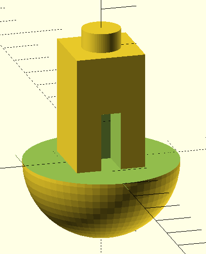
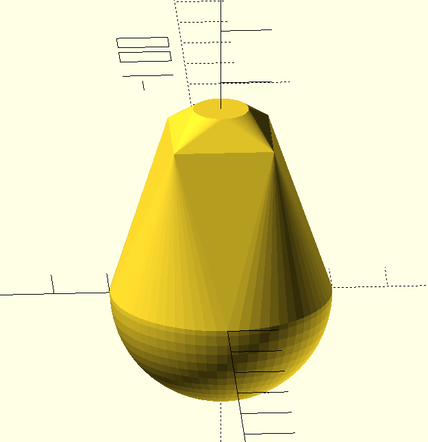
Have a look at the object to the right. Using a conventional fused deposition printer, how would you print the object? There’s no flat surface to lay on the bed without generating a lot of overhangs. That usually requires support.
 In theory, you might be able to print the bottom of the sphere down, but it is difficult to get that little spot to adhere to the bed. If you have at least two extruders and you are set up to print support material, that might even be the best option. However, printing support out of the same material you are printing with makes it hard to get a good clean print. There is another possibility. It does require some post-processing, but then again, not as much as hacking away a bunch of support material.
A Simple Idea
The idea is simple and — at first — it will sound like a lot of trouble. The basic idea is to cut the model in half at some point where both halves would be easy to print and then glue them together. Stick around (no pun intended), though, because I’ll show you a way to make the alignment of the parts almost painless no matter how complex the object might be.
The practical problem with gluing together half models is getting the pieces in the exact position, but that turns out to be easy if you just make a few simple changes to your model. Another lesser problem is clamping a piece while gluing. You can use a vise, but some oddly-shaped parts are not conducive to traditional vise jaws.
In Practice
Starting with an OpenSCAD object, it is easy to cut the model in half. Actually, you could cut it anywhere. Then it is easy to rotate half of it so the cut line is at the bottom of each part. That doesn’t solve the alignment problem nor does it help you clamp when you glue.
The trick is to build a flange around each part. The flanges mate with a few screws after printing so alignment is perfect and bolts through the flange holes can keep the parts together and immobilized while your glue of choice sets. The kicker is that I even have an automated process to make the design side of this trick very easy.
You might cry foul. After all, this is just another form of support right? Not really. At least, not in the sense of support generated by programs like Cura or Slic3r. Slicers automatically generate support that uses a special pattern made to make it easier to tear away but it contacts all the surfaces that are overhanging. Unless you use a second material and a solvent that can attack your support but not your main part, you are going to have scars all over the part. With the flange method, you have a small number of beams that connect the flange to the part. The beams are easy to remove and while they may leave a little scar, they are easy to remove since they are small and only in very specific places.
Does it Work?
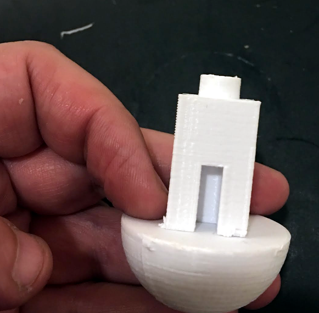 I’ve actually used this technique on a few practical projects. Although the part I printed for this example is just a test object, it shows the results of the technique quite well.
There are a few marks where the flange beams joined the main part, but they were easy to file away. If you had printed this in any orientation with traditional support it would have taken a lot more time and effort to get to a similar appearance, if you could at all. With the flange method, I simply applied some glue, inserted two screws, waited a bit, and then cut the flanges off with flush cutters. The whole process took under five minutes although some glues can take longer, of course.
I didn’t do any filing or sanding, so with more effort this could look even better. I also dinged the sphere a little bit pulling it up from the print bed (BuildTak works almost too well sometimes). However, the part still came out fine and prying a part off the bed aggressively is always a problem. It doesn’t factor into this technique.
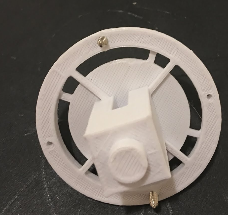
Here’s how the parts looked coming off the print bed: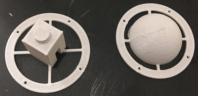
How To
Of course, now that you know this trick, you could just cut your models manually and build the flanges and support structures. That’s how I did the first one a few years ago but ever since I have wanted to automate it. Ideally, it would be great to have an OpenSCAD function that just “did the work.” I didn’t quite get there, but I did build a framework that makes it pretty easy. I put the entire file on GitHub.
The framework assumes that you have a module called part that defines your object and should be cut on the XY plane. Of course, if you don’t have that form, it is easy to wrap your code in a module and rotate and translate it to the proper point. Here’s the module for the test object:
// This is the odd-shaped part in question
module part() {
 union () {

difference() {
 sphere(r=20);
 translate([-20,-20,0]) cube([45,45,20]);
 }

difference() {
 translate([-9,-9,0]) cube([18,18,30]);
 translate([-2.5,0,0]) cube([5,25,15]);
 }

translate([0,0,30]) cylinder(r=5,h=5);
 }
}
If you prefer, you could call that module something like part0 and then write:
module part() {
 rotate([0,0,0]) translate([0,0,0]) part0();
}
Of course, you’d change the [0,0,0] parts to suit where you wanted to cut.
The rest of the OpenSCAD file has the code to cut your part in pieces, flip them, and add the flanges. There are some variables you can set to control things:
// Flange parameters
od=60; // outside diameter
odr=od/2;
id=48; // inside diameter
idr=id/2;
flangeh=2; // height of flange
flangeboltr=1.9; // size of bolt holes
flangebeamw=2; // width of flange beams
flangebeamh=2; // height of flange beams (usually same as flangeh)
flangerotate=34; // rotation of flange beams

// part offset
offsetx=50; // put the other part this far away
offsety=50;
bigcutbox=1000; // box used to cut away half the model; just has to be bigger than model
Of Interest: The hull() function
 If you want to dig into the OpenSCAD code, most of it is pretty straightforward. There’s only one part that is a little tricky. You can assume that the part is flat where you split it, but you can’t assume that it is solid. Initially, I just built the flange and beams and merged them with the part.
However, in the test object, this doesn’t work well. See the cutout on the face of the box? If you just merge the flange, the beams will exist inside that cutout! That is hard to remove and serves no purpose, so it had to go.
Subtracting the part doesn’t work because the cut out is empty and subtracting empty space doesn’t help you. The trick is to find the maximum points of the part using the hull() function. Technically this is a convex hull, but I like to think of it as an envelope. The figure on the right is the result of using the hull function on the test part.
Armed with that, it is easy to subtract the hull from the prototype flange and then merge back the original part:
 difference()
  {
  flange(); // add flange
  hull() part1(); // but cut away "outline" of part
  }
 part1(); // now add part
Post Processing
You can control where the beams intersect the model by changing the rotation. You could also comment out some of the beams for many models. Fewer and smaller beams are better because it reduces the mess when you cut them off. On the other hand, if the beams are too tiny, they will break off when you remove the part from the bed, so there is a trade-off.
 I used two small wood screws to hold the pieces together for gluing. You could also use a nut and bolt if you prefer. I usually start the screws or bolts but leave a gap. Then I apply glue to the parts while there is still a gap between them. Tighten the screws and then wait. Obviously, you have to do any surface preparation appropriate for your glue of choice. I was using DAP RapidFuse with PLA, but you may prefer other materials or glues.
I usually unscrew the pieces to make sure the glue held before I remove the beams. If you are certain of your glue, though, you could just cut the flanges free. A pair of flush cutters will make short work of the beams and leave very little residue if you use them right. If you were really wanting things to look good a little sandpaper or an emery board would vanish those beam marks easily.
Other Ideas
You can hack this idea a few different ways. For example, if your printer doesn’t like to make nice circles, you might prefer a rectangular flange. You might want fewer beams or more alignment holes. If your parts are hard to figure out alignment, you might put a mark on the flanges to identify which part goes with what. In the test part’s case, the bottom can rotate freely and it doesn’t matter and in most other cases I’ve done this, the part only goes one way and that way is very obvious.
I don’t know enough about glue science to know if you could do something interesting to the surface during printing to make it hold glue better. For example, you could create little interlocking channels to create more surface area for bonding. You could leave pockets for some sort of glue catalyst. Maybe flat is best, I simply don’t know. Maybe [Dan Maloney] can help.


Interesting problem. Myself, I would have printed a two-part inverse support model: one as a cube with a round hole in it, and another as a large cylinder with a square hole in it. Each would be used as a support insert right at the moment the printer needed the support. To ensure the parts didn’t stick together, I would use Kapton tape. The new layer will print on it, and you can easily remove the support parts from it.
So the sequence would go: print the model upside-down starting with the small round cylinder. Once complete, have a small dot off to the side inserted into the model so the print head can move out of the way at that exact layer. Pause the printer and insert the support part. Let the printer build up over the support part until it reaches the last layer of the square tower. Have another offset point in that layer to move the print head away and pause. Drop in the second support part and continue.
Kapton is thin, but should be considered in the layer stack order. Perhaps the slice thickness could be matched? Depends on your setup I suppose.
Capton is VERY thin. At least the stuff I have. We tried measuring it. After I had gotten “0” as a reading my friend pulled everything away from me and did the measurement properly. 0.
Internet says: 0.03 mm. My measurement would’ve shown that. So I suspect my capton tape is thinner than whatever the tape was found by google. Dupont sells capton from 12um to 120 um. The common stuff is MUCH closer to the lower end of this range.
It’s made in a variety of thicknesses, and the thinner ones are the low cost ones you’ll find on ebay, amazon, etc…
i got a big roll of wide kapton tape that matches my bed’s width. it was incredibly thin and didn’t hold up for one print. you could either shred the kapton or the print wouldnt stick. so i just took it off and went back to blue tape. best go with the thickest piece of kapton you can get your hands on.
for a second I was picturing the shipping costs on a queen-sized roll of kapton tape…
What exactly did you try to measure it with?
Traditional calipers of any kind are way out of their league on this, even micrometers will probably struggle to give an accurate reading on just one layer.
Stack up several layers and measure, that should get you a valid reading.
odometer
You can just put two on the slicer bed mirror of each other and lower them below the bed half way. It will only print what’s above the bed so you get two perfect haves without any special work. If ABS, acetone them together otherwise glue and a heat gun to smooth the seam.
Hey Chuck. Yeah that doesn’t do the alignment and clamping, though. You can make mating pins etc to handle the alignment but that still leaves the clamping. And — unlike some of the other suggestions — this can be practically automated relative to waiting to slide support pieces in, etc.
I like this method for when you have an STL and you don’t have the design files.
nice.
you could make the spacing of the holes in the flanges uneven, so that there’s only one way for them to match up. even if it’s “obvious” how they line up, a tiny numeric adjustment upfront could completely eliminate a possibly failure mode later. marks wouldn’t hurt, but can still be accidentally ignored as you flip the part back and forth.
I would put the 3D printer on it’s side, attached to a g-code controlled horizontal shaft. The shaft rotates the whole 3D printer so the X/Y movement is always aligned with gravity (vertical). Maybe add a slight tilt so there is an adjustable amount of gravity pushing the overhang towards the print head.
This really is the best and most practical way.
Absolutely the most practical, working out the backslash compensation for a rotating 3D printer would take a couple years but the results would be totally worth it :-)
I somehow missed it, but a similar 3D printer has already been on HaD:
https://hackaday.com/2017/01/19/3d-printer-with-tilted-bed/
It’s a very good idea. I wonder if you could just attach the flange to the bottom of the cylinder on a full model, or make a 3D flange that had some arms that came up at a 45 degree angle to add additional rigidity to the cylinder as it got larger.
Kinda not understanding how any of this really buys you anything. Cutting models apart and gluing them back together has been around for a while and is a pretty common approach if you’re not doing dual material/dissolvable supports. In this example the flange on either piece really doesn’t buy you anything other than a non-symmetrical knub you have to deal with versus a raft/support. In Simplify and others you can tune your supports to make them more pleasing, or you can even crank one out to your liking in OpenSCAD. The advantage to doing a traditional raft/support is you get a symmetrical pattern on the bottom when you break it off. Not trying to be Billy Buzzkill just not seeing how this buys me anything.
Let’s consider another example: a part that is too big to be printed in one piece on your printer. This method not only lines the two pieces up perfectly but also holds them in perfect alignment while the glue sets. Basically, it is a substitute for a holding jig. Pretty clever, really!
I weld the parts together with the MP filament pen. I make a bevel on each side & fill with the pen set to the lowest speed. I do this to avoid supports and to assemble parts of print that don’t fit. I turn down the bed temp when the mating side is down so I don’t get that a little bit wider at the bottom effect.
Good tutorial but I’m not sure why you needed the structure with screw holes. Treat your model as two distinct parts and put registration features to align the two. Bonus it’ll give you more surface for bonding.
The problem with adding registration features is that the mating surfaces need to be flat in order to print properly, he is using the mating surfaces against the heated bed as the base of the print.
I suppose that you could include negative spaces for dowel pins, but that would either add something foreign to the print in the case of steel dowel pins or would require an additional print to the side.i suppose that some 3mm filiment could also work if you cut it into cylinders…
Why not just put some matching 3mm holes in the pieces after they are cut in half? Use short lengths of filament for pins when gluing. Clean the holes with a drill if necessary. Clamping is still required, but holding by hand if using super glue or multi-purpose pipe cement is usually sufficient and easy. Now the only ugliness is the seam.
Using filament as pins is a great trick. On a large two-piece print my friend used threaded rod and glue, that build is very sturdy.
You could just make STl files for the flange parts.
To use them:
1) Drop the flange part on the Print Bed in Cura/Repetier/etc. . .
2) drop the part to be split on the Print Bed in Cura/Repetier/etc. . .
3) Split the part however you want.
4) fuse the pieces in the software
No need to go mucking about with extra software when the GUI for most slicers can do the steps for you. Your method works fine if you want to remix and and save a part for someone else to print without mucking about on their steps, but for a one-off use it seems too much.
I considered this because I do the same thing with anti-warp ears. The issue is when you get things with the holes like in the example. The flange parts then show up in the holes.
This is a good idea, I might have to use this on some tricky pieces.
One thing I have been meaning to try is some traditional joinery techniques. If you left holes in the flat of the sphere and the legs of the arch, you could print a small piece to hold them together. Or perhaps just a piece of filament like a dowel.
The shared method would seem to work over many different parts. With the test piece I would have simply made the square prism longer and differenced a bit from the mushroom head then inserted it and held it with glue.
Intesting way of doing it. But I am sure, like me, most have been chopping models in half and gluing them. I often put a hole in them and use a dowel to help connect them together.
That’s a much better method than this ring thing. If it’s a rectangular hole and dowel it would align the angle as well.
Agree, I think the dowel method is much simpler, less wasteful on filament, more precisely alignable and stronger than a flush glue joint than the flange method presented here. Simply subtract a small cylindrical hole in the legs of the top part of this model, same in the hemisphere and run off some cylinders which don’t even need to be any particular length, a bit of extra depth for the holes is fine.
I recently printed this classic Sonic Screwdriver which uses dowels to align the parts, it went together perfectly:
https://www.thingiverse.com/thing:1228924
I agree that using filament dowels is a better alignment method when you have appropriate mating surfaces, but what if you don’t? …and even if you use dowels, using a flange as well makes sure that you can clamp the pieces together firmly and evenly.
Brilliant!
Interesting articles for those with 3D printers, and thanks to the tech-specific comment section here it’s a good place to have such an article, so kudos.
Why I mention this? To offset all the time we bitch of course :)
Happy New Year HaD.
“HaDdy New Year!”
B^)
Happy New Year, Whatnot!
You got some under-extrusion on those parts
Very cool idea! It does cry out for a smart script to improve it beyond this. Thanks for getting us started
i usually just stick some screw holes in the parts. then rummage though my hardware bins for the right kind of screws. its so much easier to build sub-assemblies than it is to try and print it all in one piece. usually also makes it print faster and save plastic because there is a lot less support material. and failed prints dont waste as much time and filament.
I see ideas evolving. I like the flange and the holes. I can see that being just the ticket for some things. The nice thing about that is that you can automate that process. I also like the idea of having a pin or pins and holes in each half of the part, thought at seems like more work and it would not necessarily for every part. I don’t see either idea as the holy grail but they are good tools to be aware of if you wind up wanting to print an otherwise hard to print part.
I’ve done the whole slice it in half and print two halves thing and the seam is always like a cheap cast part. It seems like the bottom few layers are a little wider than the rest. I’ve messed with settings a little bit and can’t seem to dial it out. It’s not horrible, but noticeable.
I already do this and it also happens to be with openSCAD designs. Kinda’ common sense, no? The issue is reliably gluing PLA. I’ll have to try DAP Rapidfuse (are you using the DAP 00155 type?) although I use Loctite Ultra Gel Control Super Glue based upon an adhesion test done by someone on YouTube that showed it to be the clear winner by far. They didn’t test DAP Rapidfuse, unfortunately. I just did a Google search for “dap rapidfuse pla” and found nothing.
The dap holds well. Walmart. Blue tube like super glue.
The other I keep meaning to try is JB weld plastic bonder.
I see this as a design issue. If you know you will be 3d printing the part in question, then you need to design for 3d printing. Its easy enough to design the part to be printed as 2 pieces. The trick is to build alignment into the design. For this shape being printed in 2 parts as you have it laid out, I simply would have put a square inlay inside the sphere and made the square a little longer to match the depth of the pocket. A dab of glue inside the square pocket and its never coming apart and has perfect alignment.
If the part was cut length wise then using an offset and extruding 1 side while cutting the opposite would also provide a perfect alignment and again be much stronger than a flat face “butt” joint. Takes about 30 seconds to create the offset, extrude 1 side, then extrude(cut) the opposite piece using the first as the cutting tool using fusion360.
Would it not be a lot easier to just cut the model in half, as you suggest, and then draw up a wee bit of a hole pattern. Make the hole diameter… oh, I don’t know, 1.75mm… maybe 1.77mm. Extrude the hole pattern in both directions and print the parts, flipping the appropriate one upside down. Both parts would have exactly matching holes. Then, all you have to do is find some 1.75mm plastic, something or other.. might be able to find some of that kicking around the workshop, somewhere… then stuff it in the holes for alignment, and then glue the thing together. Nothing to trim, no filing, no screws, nada…
yeah the best source or 1.75mm rod i found was right in the extruder, when i swapped my spool. it even had nice notches on a few inches, to better grip the glue.
Hi,
Thanks for sharing this nice post. It’s really a helpful content for those who always need 3D prints for their personals. Really so easy steps you have shared here. Mostly I am always contacting iannone3d.com for any of my 3D requirements. But after your post, I thought to do it for myself.
Thank you