The Creality CR10-S is a printer that has become quite popular, and is not an uncommon sight in a hackspace or makerspace. Some models have a slight defect, a smoothing capacitor is of insufficient size, resulting in reduced print quality. [Jozerworx] has replaced the capacitor, and posted a full guide as to how the task can be performed.
Hackaday readers will have among their number many for whom replacing a surface mount electrolytic is no bother at all, indeed we’d expect most 3D printer owners to be able to perform the task. Maybe that the post has such an extensive FAQ and seems to be aimed at newbies to soldering points to 3D printing having moved to a wider market. But it has to be remembered that the value in this piece is not in the work, but in the characterisation. At the end he posts graphs showing the effect of the modification on the temperature of the extruder, and on the temperature noise brought about by the poor capacitor choice. A reduction from a +/- 3 Celcius variation to one of around +- 0.1 Celcius may not seem like much, but it seems it has a significant effect on the reliability of the printer.
So this isn’t the most elite of hacks, on a printer heading for a wider marketplace. But it serves to illustrate that bad quality power regulation can have some surprising effects. It seems every new printer comes with a list of community-developed mods to make it usable, perhaps one day we’ll find a printer that’s at peak performance out-of-the-box.


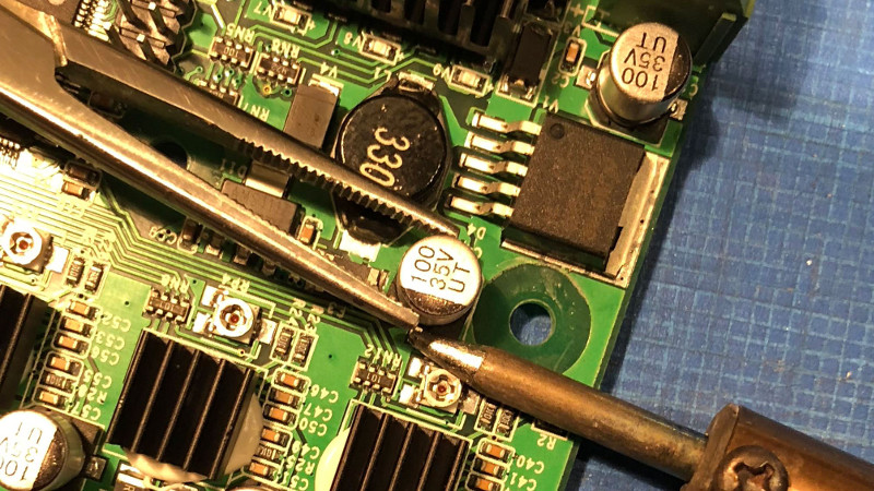
Except I wouldnt want to press that iron against the potentiometer like that….
Never fear, the iron was off and cold when I took these pictures. Had to do everything twice, once to photograph and once to actually do the soldering. Hard to position the iron with a camera in the other hand :P
I had a disclaimer somewhere on mines that read something like:
“All pictures shown are artistic recreations for illustration purpose only”
+1
Its a capacitor not a potentiometer.
The bit with the phillips socket the iron tip is on top of *is* a potentiometer. (used to adjust voltage of stepper driver directly below it under the little heat sink…)
Who need desoldering lead-free caps when you can twist it. https://www.youtube.com/watch?v=X8N9O3a9jiM
So, is that the correct pronunciation of “Solder?” If so, where are you from?
Based on his pronunciation of “without” I’d assume he’s from Canada. I’ve heard Brits says “solder” with a hard L but didn’t know Canadians also did it.
We’re an inconsistent lot when it comes to english. Mostly British spelling, mostly american pronounciation. emphasis on “mostly”
We are all very nice. But All messed up. Love Hockey and bear.
The French Canadian are the most messed up.
I am a North American all the way back to 1642. That’s when My family came to North America.
My family has been slottered and force matched back and forth across the border, In the Olden Days.
We have over 15,000 names in our family tree so far and growing.
And there is a good chance that I am related to you.
WOW what were we talking about again..??
Oh Yea.
Nice work. I have to look at the printer I had gotten at the used store.
That is something I will look into because there is a problem with the power supply.
Thanks
That was beer not bears….
dame fingers.
@Perry Levac – Bears worked too, your neighbors south of you always point that out … LOL {Ducks Thrown Shoe}
Why desolder? Because in this case, the repair is because the as shipped capacitor is not as well matched to the job as the replacement, not because the as shipped capacitor is dead. By desoldering, you have the chance to reuse the original capacitor
Yeah you always need backup way. But main point is avoid heating PCB (especially modern one with solid ground layer). It quickly become bubble w/ risk to break inner layer trace. Or you can have expensive preheater and replacing one cap is become long journey. BTW many electronics repair shops now mill out defect IC instead desoldering.
Nice trick, I would be afraid to tear the pads through…
“A reduction from a +/- 3 Celcius variation to one of around +- 0.1 Celcius may not seem like much, ..”
Maybe a 3 degree temperature difference might not seem much in Fahrenheit, but in Celcius that’s quite a bit, in human comfort terms at least. imho.
Eh not really, temperature perception is really dependent on humidity. 23C indoors can be perfectly comfortable at low humidity, or somewhat unpleasant at high humidity. 3 degree swing is noticeable, but not overly so.
Just because there’s a dependent variable doesn’t mean the primary variable isn’t also a big concern. With humidity held constant a 3deg swing can be the difference between jumper (19C) and just a t-shirt (22C)
+/-3 -> 6 degrees variation
+/- 3C = +/- 37.4°F or a total swing of 74.8° F and it doesn’t matter what the humidity is.
Uh, no
You cant just convert C to F, the zeros of the scales don’t line up. The true swing is about 10F.
-17.778C = 0F
-17.778C = 5.4F
Fun fact, if you attempt to remove these with hot air, poke a hole in them first. Otherwise they explosively remove themselves from the PCB.
If you’ve had surface-mount capacitors explode from attempting to remove them with hot air, your temperature is waaay too high. These capacitors can be soldered with hot air! No hole poking required!
If you are removing them, it’s likely because they have gone bad. When they go bad, they temperature at which they will rupture becomes much much lower.
Not in this case- the capacitor in question is still good, just too small.
It’s spelled “Celsius.”
It’s a lost battle, no matter the spell checker’s squiggly red underscores. Even the Swedes spell it wrong and the guy was Swedish!
It’s nice to see really good step-by-step writeups.
About the only comment I’d make is that, depending on how much room there is for the circuit board, it might not have been necessary to remove the original capacitor. Capacitance is capacitance; it could be simpler to simply tack on another capacitor in parallel. This might require flying leads, and maybe a touch of glue to secure the added cap.
Also it would be cool if somewhere there was a before and after ‘scope image of the ripple, to show the change.
“A reduction from a +/- 3 Celcius variation to one of around +- 0.1 Celcius may not seem like much” … um no, that’s a huge improvement, if that’s truly the difference.
The guide I wrote up is targeted at beginners, so I didn’t include details which wouldn’t be directly applicable to the task at hand (fixing the printer). Out on the CR-10 user groups, a few people have posted oscilloscope screenshots capturing the ripple before and after changing out the capacitor, and things look significantly better.
Don’t suppose there’s an easy way to see if you’ve got the wrong capacitor without disassembling? I’ve bought one and assembled it but not tried running it yet. First 3D printer and I don’t mind admitting the thought of desoldering surface mount caps on an expensive new piece of kit fills me with dread.
See the FAQ on the blog entry.
Hello, I’m not a CR-10 owner and I’m not at all familiar with it, but I am curious about this fix. Normally I’d expect 100uF to be sufficient on the 5V regulator for a board like this. I’m pretty sure I’ve seen that value used on a number of similar boards. I’m just guessing that the temperature is read by an ADC in the microcontroller? Is there a schematic available? My real question is: Was the AVdd power pin(s) on the microcontroller isolated from Vcc, as is usually recommended, with a ferrite bead and cap on the AVdd side?
I’ve been involved in this since the problem was first detected in December (I was one of the lucky first few. Lucky me, LOL)
The LM2596S that Creality used is a cheap Chinese knockoff with a 20% tolerance. As are the caps. According to some EE’s that examined the issue, Creality did not (as many companies don’t) follow the design specs for the LM2596S, which calls for a 220uFd output cap as part of the filter. Why? Because ALL the other caps are 100u, cheaper to stock just one cap. When you’re buying in quantity and making thousands of printers …
Well, combined with the board design, no doubt, the cheap reg and low cap created a perfect storm. Some machines were fine (parts were dead center of tolerances I’d guess, or the cap was high), others like mine required the cap replacement as well as using a Texas Instruments LM2596S rather that the cheap junk they used.
Schematic – nope Creality isn’t releasing it, just like until two weeks ago they refused to release the Source Code changes that they made to Marlin in violation of GPL licensing laws. A grassroots campaign and the not inconsiderable intervention of Naomi Wu (aka @SexyCyborg) caused them to finally release it to the public. Yea! They literally did not get that it was illegal for them not to release it, she finally broke through the language barrier, they weren’t being jerks, they literally just didn’t GET it, and apologized publicly in a Youtube video.
>Normally I’d expect 100uF to be sufficient on the 5V regulator
Yeah, should be, but my guess they have some ground plane, or ground loop, thing going on in an inside layer … A quick peek with my scope showed it was pretty noisy, didn’t write it down, just looked and said “Wow, THAT’s too much ripple!” Guess I should have done some before / afters but was more interested in fixing the stupid thing then doing a paper on it! LOL
There’s a new board now, the v2.1, which has a 220u cap, although there were a few released with the old 100u on the v2.1 board. Guess who was lucky enough to get one of THOSE. Yep. My luck is holding. ANOTHER cap replacement, LOL
Don’t check back here much, you can usually find me on Reddit CR-10 group.
It would be nice if I was credited for actually dedicating the time and sharing the information for this for. Jozerworx merely just wrote up the DIY guide. I did ALL the leg work and analysis on this issue. The information CC 4.0 Attribution license so please respect that and put a link back to my article here: https://www.th3dstudio.com/knowledge-base/cr-10s-v2-0-v2-1-temperature-repair/
Forgot to include the link to the article with my scope images. https://www.th3dstudio.com/creality-cr-10s-v2-0-and-creality-cr-10-v1-1-2-board-issues/
I bought what was advertised on Ebay as a CR-10S, but after unpacking and assembly, I had problems with Z-Axis motors, so checked inside the controller, only to find that I had a CR-10 with a V1.1.1 Board. I was advertised that this board did not have enough power to drive two Z-Axis motors. It is to costly to send it back, the freight will be more than the cost of a new motherboard. So I purchased a V2.1 Board from AliExpress.and downloaded a copy of this version of the board, only to find that it is using the same capacitor as V2.0 Board that your information refers to.
Do you think that the later version board will have the same problem? A difficult question I know.
The second use of the word advertised, should read advised, as “I was advised”, sorry about that,
There are probably a number of different factors here. Cheap dodgy regulator IC, possibly dodgy loose PCB layout, inadequate bulk capacitor, ESR of the bulk capacitor too high, or no small ceramic capacitor (low ESL/ESR and good high frequency characteristics) in parallel with the bulk capacitor. But use a genuine regulator and read the data sheet – sometimes you don’t want the ESR too low and the ESR has to be kept within a specified Goldilocks zone.
For the skeptics including myself I spent 3 days analyzing the issue. i made lots of before and after measurements and can say that it fixed my cr10s V2.0 board.
The skeptic in me was fueled by the intermittent nature of the fault and to confuse the issue had just firmware updated and printed ok just prior.
Finally i replaced C4 100uF SMD with a 220uf thru hole (just sharp bent the leads outwards and trimmed close to the can. Will follow up with some hot glue to help fight vibration fatigue.) and the noisy thermistor measurements all but disappeared. The cr10s no longer throws errors and can maintain PETG level setpoint (242degC in my case) me. i used key hole surgery so did not remove the board/cables etc., just the PSU.
Thanks for sharing a great article.