Switches seem to be the simplest of electrical components – just two pieces of metal that can be positioned to either touch each other or not. As such it would seem that it shouldn’t matter whether a switch is used for AC or DC. While that’s an easy and understandable assumption, it can also be a dangerous one, as this demo of AC and DC switching dramatically reveals.
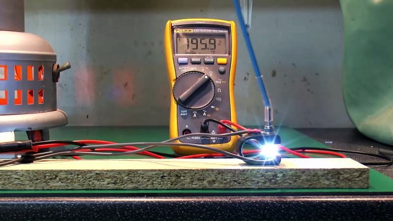
Using a very simple test setup, consisting of an electric heater for a load, a variac to control the voltage, and a homemade switch, [John Ward] walks us through the details of what happens when those contacts get together. With low-voltage AC, the switch contacts exhibit very little arcing, and even with the voltage cranked up all the way, little more than a brief spark can be seen on either make or break. Then [John] built a simple DC supply with a big rectifier and a couple of capacitors to smooth things out and went through the same tests. Even at a low DC voltage, the arc across the switch contacts was dramatic, particularly upon break. With the voltage cranked up to the full 240-volts of the UK mains, [John]’s switch was essentially a miniature arc welder, with predictable results as the plastic holding the contacts melted. Don your welding helmet and check out the video below.
As dramatic as the demo is, it doesn’t mean we won’t ever be seeing DC in the home. It just means that a little extra engineering is needed to make sure that all the components are up to snuff.


he did another video demoing the effect on a UK light switch.
https://www.youtube.com/watch?v=CUFVSc5ll4s
why?
Alternating Current (AC) changes direction every “cycle”, Direct Current (DC) flows in one direction and remains constant.
A spark (arc) occurs as the switch contacts make or break contact. An arc is plasma (heated, ionized) (I was going to say it was a “gas”, but one instructor told us that plasma is considered a 4th state of matter (gas, liquid, solid, plasma).
Anyway, AC drops to zero current twice each “cycle”, that can/does extinguish the arc. DC does not alternate so it doesn’t drop to zero. It’s arc will die if the distance between the contacts it great enough.
Think of the “Jacob’s Ladder” in old “mad scientist movies”. It’s two contacts get further apart as height increases, eventually the distance is too great and the arc extinguishes (and a new arc starts at the base). The arc moves “up” the Jacob’s Ladder because hot air rises.
In older automobiles, under the distributor cap was a set of “points” (really switch contacts) and a “condenser” (a capacitor).
As the contacts opened to fire the spark plugs, the points/contacts became pitted and worn from the arcing. The condenser/capacitor was across the switch (contacts) and gave the current a momentary “bypass” of the contacts which prevented the arc from sustaining (therefore easier on the contacts).
So, every “tune up” back then included replacing the points, condenser, distributor cap, and spark plugs, because all the High Voltage DC running through them wore them down.
This is a very good question most answers i have seen are sort of correct. These high voltages
In dc relate to faradays law, even with just straight simple wiring there is still a finite inductance
When you try to switch off dc current the rate of change of current tries to go from
A finite current to zero in microsecs, say 10 amps in 1 microsecs this gives 10 million amps
Per sec change multiply this by say a 10 milli henry inductance and you have a back emf of
100,000V. With ac at 50 hz you have a change of current of 200 amps per sec at 10 amps.
This example is made up but it comes back to Faradays law which is one of Maxwells equation
Here’s why you won’t see DC power distribution:to your house:
– E=IR (it’s the law)
– The higher the distribution voltage, the less loss in the distribution network (because lower current)
– You don’t want kV in your house, because insulation for that takes up space (and other reasons)
– So, low voltage and higher current at the point of use, higher voltage and lower current in the distribution network.
– transformers solve the problem nicely, but they only work with AC
– So, AC is better than DC for power distribution to the user
–
But most voltage transformation within a home these days is done by first turning the Mains AC into DC than manipulating it to another voltage.
Thats because DC is more convenient for that application., DC is not convenient for local infrastructure.
POE+ lighting*
*look it up.
Nowadays there are close to zero appliances in a regular home that still really require AC. (Microwave) Ovens and Stoves. Everything else is or can be powered by DC, yes, even lights. Which means that in theory you could be running DC throughout your home, eliminating all those pesky wall-warts and their inefficiencies.
The reason why that’s not really appllicable is because low voltage DC and high current doesn’t go too well together unless you’re having excessively thick wiring. Thick wiring costs more money. Powering a 500W appliance by feeding it 230V@2.2A AC is cheaper than feeding it 12v@42A DC. If in doubt, the reason is cost. It’s that simple.
Resistive heaters work just as well on DC, the problem is the switching device that has to interrupt the current.
Microwave ovens also use (high voltage) DC.
My off-grid house has dual circuits: 240VAC power (supplied by the inverter), and 24VDC (unregulated straight from the batteries) for light + power. The wiring is identical – the usual 2-core+earth capable of carrying 10 amps.
It means there are actually more DC cable runs to make sure no single run carries more than 10 amps, but it’s cheap because It uses cable designed for 240VAC instead of dedicated DC cabling – the earth strand is terminated and taped off. The DC circuits look more like a star than a ring – there’s at least one DC cable run from the batteries to every room, whereas the AC cable run is more of a ring.
The DC bus is adjacent to the AC bus. Because it’s the same cable, I can switch a circuit from DC to AC by moving the cable ends from one bus to another (after de-energising all the circuits, of course).
Now, is a 24VDC circuit much use? Not anymore, because 24-volt light bulbs are expensive and hard to come by, but it wasn’t always that way. I’ve still got a 24 volt refrigerator that just keeps working. And, I can now buy 8-30 volt drop-in LED lamps, so that’s good. I could also put in some voltage regulators/converters for a lot of purposes – 19 volts for my laptops, 5 volts for USB ports, 12 volts for various common appliances, and so on. There are lots of practical uses for low-voltage DC circuits in your house – but it’s probably too expensive to retro-fit. Fortunately for me, the fellow who built this place was both adventurous and open-minded. It didn’t hurt that he was also the actual builder, so he could install these things without a lot of fuss. Not too many inspectors would be able to pick up that the cable that looks just like regular 240-volt cable was actually carrying 24 VDC.
On the other hand we have HVDC to do the same job so maybe in a future… who knows?
https://en.wikipedia.org/wiki/High-voltage_direct_current
I used to work on electrified railways (the London Underground : The Tube), which use 600v DC to power the train motors. The switching was done using mercury potted relays – metal fingers which rotated in/out of pots filled with mercury. Obviously this arcs but now in a way that matters, as long as the mercury ‘splashes’ are controlled. In the 1980s without good old health and safety we used to have to maintain these relays, and so carry tubs of spare mercury in our toolbags to top up the relays. Bizarre, eh?
I’ve worked with mercury relays used for switching process heaters in lamination presses (many, many years ago), but those were all sealed. Occasionally one would blow one phase and needing replacement. The old ones usually went into the trash! Needless to say, I grabbed all of the dead ones that I could and recovered the mercury out of them for home use (playing around with…). Not sure what would be used in place of those relays these days, probably some sort of solid state relay.
Mike.
Thank you for this comment.
I am in the med-High voltage industrial switch-gear industry.
However, I am only 24, so naturally I have never even heard of these relays you speak of.
I learnt something new and awesome today because of you.
So, thanks.
For some real fun, google how they got the 600V DC. Mercury Arc Rectifiers.
Hooray for Tesla (:
And Edison murdered animals with AC…
So, supposedly I have 300A of current at 7V flowing through a coil. How would you turn it off without explosion?
I mean, it doesn’t have to be mechanical switch. Could you use something electronic for that?
unplug it VERY slowly
Or very fast
just use a beefy regular contactor (Even one for AC), it may be DC but its only 7v so it wont maintain an ark, especially if your have a snubber diode to stop the flyback voltage spike.
Depending on duty cycle, an automotive starter relay might be the way to go.
NO,
DO NOT use a contractor to break a circuit, they are not made for that purpose.
I dunno, some of the contractors I work with are definitely made for it!
It’s when the contractor “completes” the circuit is when things can get smelly!
B^)
You can put a load across the coil with a resistance that is low enough to dissipate the energy stored in the coil, and not too big so it doesn’t blow up everything.
It used to be common to put resistors or small light bulbs across relay coils to avoid sparking (and adding a visual troubleshoot feature).
I could be wrong, but I think it is a common practice to place a ‘flyback diode’ across inductive loads.
https://en.wikipedia.org/wiki/Flyback_diode
It’s better to use anti-series tvs rated at 2x the coil voltage with the diode, ie VL = L * dI / dT. If you allow the VL to get higher when the switch is turned off, the inducance will discharge faster.
Some dc applications use multi pole relay wired back through its self. You may use a 3 pole relay to turn on/off 1 line dc, using all three poles wired in series increases the arc length by 3x thus extinguishing the arc quicker. I have seen this done on older 400 v dc crane equipment to prolong the life of the relays.
Magnetic arc quench relay…
Same principle with fuse voltage rating.
Many switches that handle high current DC have strong magnets built-in to ‘blowout’ the arc into ‘arc chutes’ and a sacrificial electrode that takes the brunt of the discharge damage. The magnet effectively forces the arc to take a much further path. The ‘blowout’ name comes from larger older designs (still in use) that use compressed air to blow the arc into the arc chutes/splitters.
If the capacitors in his setup were removed, the DC results would be no different thanAC. Food for thought.
‘If the capacitors in his setup were removed, the DC results would be no different than AC.’
Yes, because then it would not be DC, it would be rectified AC (Sine wave with negative going half made positive).
Once A.C. is rectified it’s no longer “alternating current” since current is no longer alternating direction.
https://en.wikipedia.org/wiki/Alternating_current
It becomes D.C. with ripple. So if the capacitors were removed so current could periodically drop to zero, the arcing issue goes away.
True; this is the reason such relays and switches often have some indication for the preferred direction of the current, because a current in the other direction would also force the arc the other way, which may be suboptimal.
Also, such relays are sometimes filled with hydrogen (which sounds like a very bad idea at first, but remember there is no oxygen present inside), which somehow contributes to the extinguishing of the arc, but I’m not sure how. I guess it’s harder to ionize into a plasma than most other gasses?
I once thought it would be a good idea to build an inverter without a transformer. To do this, I would charge a bunch of 12 V 7 A*hr batteries (the type used in UPSs) in parallel, then use relays to switch these to series, providing a really high power 170 VDC power supply. This was then to be pulse modulated and filtered to produce a sine wave. I wanted to test how much the voltage would drop under load, and bought a cheap iron to use as a load, and set up just ten of the batteries to supply 120 VDC. I turned on the iron, but I don’t remember how much the droop was, because of what happened next.
The iron, having of course a built-in thermostat consisting of a U-shaped bimetal piece and a pair of contacts. Being a thermostat, the contacts didn’t open quickly or far. As soon as the iron got up to temperature, the thermostat contacts opened. Like, a fraction of a mm. The arc made a noise similar to the one in the article, just kind of an ominous “fffffffffffffffsshhhhhhhh”, and I attempted to turn the iron off, but it would not turn off. No way did I want to grab any of the wires on the batteries, not being absolutely sure that the whole rig was isolated. After a few seconds of this, the problem solved itself: a fuse (or maybe just a weld, I don’t know) inside one of the batteries opened, ruining that battery but saving my bathroom floor, I’m pretty sure.
I took the iron apart to see just how bad the arc had been. What I saw there gave no indication of the prior violence. What was there was a single continuous contact. There was no evidence that it had ever been two separate pieces of metal.
this is why relays have higher ac ratings than dc.
That zero crossing in AC is pretty helpful.
Something that makes me giggle in video’s like this is watching the person put their fingers across the caps when they are pointing to things. DC caps can be really dangerous NEVER stick your fingers across them.
My principle is: if it sometimes kills you, don’t touch it unless absolutely necessary.
I view it from a software perspective; a needless race condition with death. Race conditions should be considered bugs, it isn’t good enough to try to win every race.
Same as streets; don’t play in the street just because you don’t see a car coming! Also if you’re walking next to a street, don’t randomly step into the street; stay on the sidewalk unless the path is truly blocked.
Or if you’re out in the woods, and you see a hole in the ground, don’t stick your hand in it! Or even step next to it.
300amps at 7vdc?
Use semiconductors, how about a crap load of paralleled MOSFETS? Wouldn’t even sweat it.
EL = 1/2 L*I*I. How much inductance do you have? You can figure out how how much you have to clamp when you turn off the fets.
DC in the home makes sense when every appliance is powered by BLDC motors and there are solar panels too your LED lights don’t need AC.
It’s coming, just not today or tomorrow.
I’m not sure what you’re saying, but obviously such low voltage and massive current has comparatively (18A @120V) worse efficiency and cost. Instead of a house wired with 14AWG, you’d need 00 AWG wire to have the same efficiency. About 100x more expensive and impossible to route through a wall. Your outlets would be toaster sized and require machine screws to engage their massive force (I use these at work).
Now if it was all high voltage, then the only issue of using DC over AC is higher cost of switches and reduced safety.
Why such low voltage and massive current? Railgun powered from lipos. Some 18650 lipos have 30A current rating.Connecting 20 as 2s10p would give you such currents (and about 10-100ms of such current won’t seriously degrade them). There will be less arcing than with super high voltages, but there still should be some way to quickly disconnect batteries in case of projectile welding itself to rails. Flyback diode won’t help here, or maybe there should be separate diode for relay. Why coil? Augmented railgun will be much better usage of such energy.
If the circuit has enough inductance, you WILL get a voltage spike across your switch device when you interrupt the circuit. How high this voltage spike goes is a function of how much stray capacitance there is – often the inductor will have enough inter-winding capacitance that it will just ring for a little bit, and the resistance of the wire will dissipate this. Even in low-voltage relay circuits, the voltage spike can be significant. In many relay circuits I’ve seen, they put a zener diode in series with a standard diode across each coil winding. This provides a nice resistive path in the reverse direction so that the coil energy dissipated quickly, both absorbing the voltage spike AND allowing the relay to drop out quickly. Many designers just put a “freewheel diode” across the coil, but this takes longer to dissipate the energy in the coil.
Using MOSFETs instead of relays alone doesn’t solve the problem; this just puts a big voltage spike across the MOSFET each time you turn the coil off, unless you turn it off slowly enough that the MOSFET itself provides the resistance required to dissipate the energy.
You want dramatic?
OK.
https://www.youtube.com/watch?v=hIkNY5xjy5k