It may be nearly 40 years old, but the Atari 5200 still inspires legions of fans to relive the 8-bit glory days of their youth. There was much to love about the game console, but the joystick-and-keypad controllers were not among its many charms. The joystick didn’t auto-center, the buttons were mushy, and the ergonomics were nonexistent.
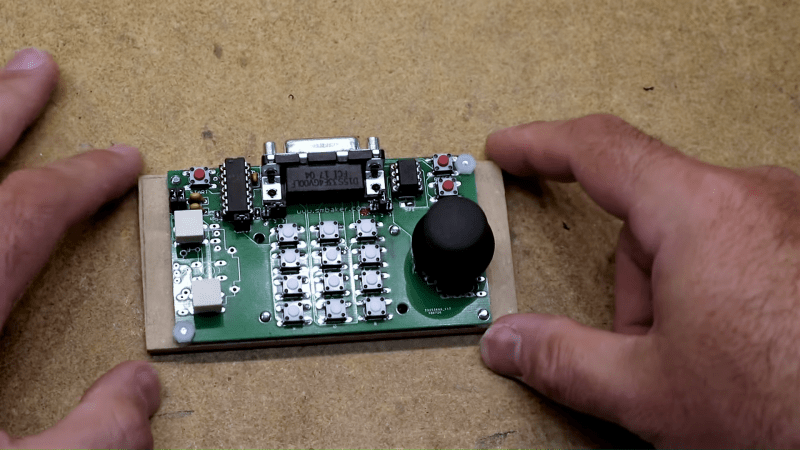
Retro-aficionados need not suffer in silence, though, thanks to this replacement controller for the Atari 5200. [Scott Baker] didn’t want to settle for one of the commercial replacements or, horrors, an adapter for the old PC-style joystick, so he rolled his own. Working from the original Atari schematics, [Scott] devised a plan for using a readily available thumbstick controller as the basis for his build. The essential problem was how to adapt the 10k pots on the new joystick to work in an environment expecting 500k pots, which he solved using an analog to digital and back to analog approach. The ADCs on an ATtiny85 convert each joystick pot’s voltage to a digital value between 0 and 255, which is sent to a 100K digital potentiometer. A little fiddling with RC constants brings it back in line with what the console expects. The thumbstick and buttons live on a custom PCB – kudos to [Scott] for designing an ambidextrous board. The video below shows the design and the finished product in action.
[Scott] is on a bit of a 5200 kick these days; he just finished up a Raspberry Pi multi-cartridge for the venerable console. His controller should make retro-gameplay on the console a little easier on the hands.


What issue was there just using 10k pots direct?
I thought it being in voltage divider config, it’ll work the same, unless it’s rheostat config.
To correct myself, its wired as an open rheostat, not a divider.
Interestingly, one set of schematics state 640k, not 500k.
Atari age forum has various flavours of measurements, and that the pot is likely a 1M ohm pot only used halfway, hence the 0-500k range.
There are multiple different pots used in original CX-52 Atari 5200 controllers. Some have a higher range than 500k but they also have a greater physical movement range so the stick doesn’t move it to maximum. You actually never hit the pots’ internal stops with a 5200 joystick. 40k to 460k is a typical range the console sees though I have seen much closer (490k+).
Never seen a 1M ohm pot but I have seen one that curiously stops increasing in value at 500k ohm well before it reaches the physical stop, which means it was probably customized/adapted from a 1M ohm pot.
I’ve seen Matsushita/Panasonic (triangle logo), Alps, and CTS-brand pots. The CTS brand ones are made in the USA and have severely degraded. I got a case of four NOS controllers with CTS pots and they all measured around 350k ohms max, which makes it impossible to play certain games (can’t stop or turn in Pac-Man) and severely harms others (can’t defend right side in Missile Command).
After reading the project page I still don’t get it.
A 10K pot is “converted” to a 100K pot using digital technology, then then 100K is made to look like a 500K by adding some capacitance. Now I understand that the atari uses RC timing techniques to measure the resistor value of the pot (which is not used as a voltage devider but just as a series resistor in the RC circuit). This technique is nothing special as it was used by many computers of the 80’s.
The technique could easily be used on any microcontroller without an ADC, all you need is a bi-directional IO-pin.
https://www.robotshop.com/media/files/pdf/rctime_app_note.pdf
The trick of adding capacitance is just a manor of making the RC circuit (dis)charge more slowly therefore the whole circuit/system behaves the same as it would with a larger resistor value of the pot.
Now what I don’t understand if why wasn’t it possible to add even more capacitance (I suspect 10 times as we speak of a factor of 10 and the RC time formulas are linear) to make the 10K pot behave like a 500K one. Although I am aware of the fact that adding to much capacitance (50 times as much as internally used) could be problematic in some ways. For instance, the (dis)charging current may be much higher and may damage parts (depending how the circuit was build). Or proper (dis)charging would be impossible due to high-current protection resistors in internally in the atari. Anyway, it would be interesting to have some more detail about that.
I have the feeling that lot’s of the reader ask themselves the question, why didn’t he use larger pot’s? That would be a really good question, although we all know the answer, the most likely is that they weren’t available. And modifying existing pot’s would be impossible, simply because of the fact that is so damn small and non standard.
I wonder if it would be possible to use an complete analog conversion method, but for that it is important to know the exact workings/signals/impedances of the RC measurement system of the atari. Food for thought…
After all those cheap and nice thumb-controllers which are flooding the internet are very cheap and very suitable and not only for atari.
I doubt modifying the thumb pots are too hard. They are usually a standard part.
Something like RS 393-885 (https://uk.rs-online.com/web/p/potentiometers/0393885/) and start with a 1M ohm resistor/calibration trim pot across it.
The A/D conversion in the 5200 is a simple scheme wherein a capacitor is tied to a digital input and charged through a variable resistor. Software controls the charge dump, then a counter in the software (game program) must keep track of how long it takes for the charge to rise to the logic HI level on the pin. Based on the time to charge, the software infers a pot position.
The original pot in the controller is 500K, in a configuration that really only uses about half of the mechanical range to effect an approximate 273K delta centered around 250K (approx range of 114K to 386K). Additional capacitance can be added to the input line, external to the console, to compensate for the shorter charge time caused by the lower 100K max resistance. That scheme works…mostly. I found that a few games didn’t like it. My theory is that the circuitry that does the charge dump can’t discharge the additional capacitance faster than the game program expects it to. As I recall, Popeye was the game where this was observed. Using a 10K thumb controller with an even larger added capacitance was totally unworkable, I think for the same basic reason.
I acquired a 1Mohm digital pot to try this same solution, thinking I’d parallel two channels if needed to very closely match the original hardware, but it’s been sitting on the shelf for years.
I’ve tried adding C. A lot. Doens’t work.
Commodore had a patent for faking capacitance analog joystick readouts (actually paddls) with digital signal in line 1987 “US4886941: Circuit for interfacing mouse input device to computer system “.
Reimplemented in 1998 using PIC micro, here are the details ftp://www.zimmers.net/pub/cbm/documents/projects/interfaces/mouse/Mouse.html
TLDR use timers, no need for analog anything.
The recurring ocurrance of controller mods and such. Is it a HACKADAY’s author’s special asset or am I the only one who finds this exhausting?
I don’t get much of a buzz from them either, but I let it pass, we each have our favorite hacks…
I don’t think you have any idea how desperately this was needed.
Atari 5200 is notorious. NONE of the original controllers work flawlessly without hacking, and building a fully functional replacement is still a pipe dream for most with no good projects out there for this.
This is the first functional solution I’ve seen demonstrated for using a modern thumb stick to support analog on 5200, yet even this one is a compromise (self-centering). Yes, Ben Heck also did this but he never demonstrated it with an analog game. There have been others translating these thumb sticks into cardinal or 8-way directions, which is only good for non-analog games.
Interesting. I was thinking of a similar mod using analog thumbstick plus digital pot but instead of 12 switches, I was going to use touchscreen LCD. Have it load off SD card the original controller overlay if used or default blank 5200 controller.
I also made an adapter to use Atari Jaguar controller on a 5200 (much easier) using ATMega328 to handle translation from Jaguar controller to 5200 system.
“The essential problem was how to adapt the 10k pots on the new joystick to work in an environment expecting 500k pots, which he solved using an analog to digital and back to analog approach. The ADCs on an ATtiny85 convert each joystick pot’s voltage to a digital value between 0 and 255, which is sent to a 100K digital potentiometer.”
Err, this approach (“the original controller has a 500k pot, so let’s replace that with a software-driven digipot in the same range”) sounds rather unsubtle, the kind this blog made a reputation to avoid… Ok it’s working, but at least put it in an appropriate section “underthought / over-engineered solution of the week” !
Instead of focusing only on the pot, while not just look at the whole but simple enough picture of the operations ? To put it straight, the console just discharges a capacitor, then count how much time it takes for it to reach a certain threshold value while charging through the controller’s potentiometer (the bigger the resistance, the higher the time and count).
With just the ATTiny, you could “pulse-charge” this counter-triggering potentiometer with a PWM (ideally with a predetermined array tailoring the charging time for each input values) or from a simple GPIO with a timer… consequently, where is the “could probably be done with a 555” obligatory mention in this report ?? Thumbs down, Hackaday ! :(
Your reporting is not timely and well-researched. This is a knock-off of a 5200 controller revealed in 2011 on AtariAge. That controller didn’t need a microcontroller. The 5200 console itself was shrunk down using a custom motherboard.
http://atariage.com/forums/topic/185369-compact-5200-system
He also recreated the trackball circuitry to use arcade parts:
http://atariage.com/forums/topic/185409-5200-mini-arcade/
10 k pot thumsticks absolutely can work. I know because I successfully did it with 2,200pF ceramic caps and 10k trimmer resistors. Scroll halfway down the page:
https://atariage.com/forums/topic/204711-new-5200-joystick-from-best/page/4/
Forget my previous post. It may have been 100k pots on that stick.