Rediffusion Television: Early Cable TV Delivered Like Telephone

Recently I spent an enjoyable weekend in Canterbury, staying in my friend’s flat with a superb view across the rooftops to the city’s mediaeval cathedral. Bleary-eyed and in search of a coffee on the Sunday morning, my attention was immediately drawn to one of her abode’s original built-in features. There on the wall in the corner of the room was a mysterious switch.
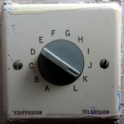
Housed on a standard-sized British electrical fascia was a 12-position rotary switch, marked with letters A through L. An unexpected thing to see in the 21st century and one probably unfamiliar to most people under about 40, I’d found something I’d not seen since my university days in the early 1990s: a Rediffusion selector switch.

If you have cable TV, there is probably a co-axial cable coming into your home. It is likely to carry a VHF signal, either a series of traditional analogue channels or a set of digital multiplexes. “Cable ready” analogue TVs had wideband VHF tuners to allow the channels to be viewed, and on encrypted systems there would have been a set-top box with its own analogue tuner and decoder circuitry.

Your digital cable TV set-top box will do a similar thing, giving you the channels you have subscribed to as it decodes the multiplex. At the dawn of television transmission though, none of this would have been possible. Co-axial cable was expensive and not particularly high quality, and transistorised wideband VHF tuners were still a very long way away. Engineers designing the earliest cable TV systems were left with the technology of the day derived from that of the telephone networks, and in Britain at least that manifested itself in the Rediffusion system whose relics I’d found.

Continue reading “Rediffusion Television: Early Cable TV Delivered Like Telephone”

3D Printers Get A Fuel Gauge: Adding A Filament Scale To OctoPrint

It seems a simple enough concept: as a 3D printer consumes filament, the spool becomes lighter. If you weighed an empty spool, and subtracted that from the weight of the in-use spool, you’d know how much filament you had left. Despite being an easy way to get a “fuel gauge” on a desktop 3D printer, it isn’t something we often see on DIY machines, much less consumer hardware. But with this slick hack from [Victor Noordhoek] as inspiration, it might become a bit more common.

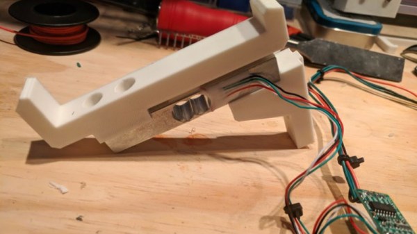
He’s designed a simple filament holder which mounts on top of an HX711 load cell, which is in turn connected to the Raspberry Pi running OctoPrint over SPI. If you’re running OctoPrint on something like an old PC, you’ll need to use an intermediate device such as an Arduino to get it connected; though honestly you should probably just be using a Pi.

On the software side, [Victor] has written an OctoPrint plugin that adds a readout of current filament weight to the main display. He’s put a fair amount of polish into the plugin, going through the effort to add in a calibration routine and a field where you can enter in the weight of your empty spool so it can be automatically deducted from the HX711’s reading.

Hopefully a future version of the plugin will allow the user to enter in the density of their particular filament so it can calculate an estimate of the remaining length. The next logical step would be adding a check that will show the user a warning if they try to start a print that requires more filament than the sensor detects is currently loaded.

This is yet another excellent example of the incredible flexibility and customization offered by OctoPrint. If you’re looking for more reasons to make the switch, check out our guide on using OctoPrint to create impressive time lapse videos of your prints, or how you can control the printer from your mobile device.

A Display Made From Shoelaces

In our time here at Hackaday, we have seen many display builds, but this one from [Brian Lough] has to be a first. He’s created a 7-segment display made from shoelaces, and it works rather well.

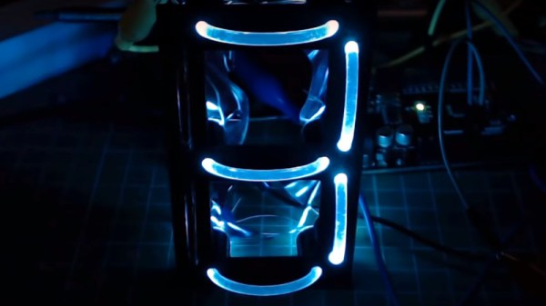
Before you imagine the fabric cords you’re used to with your trainers, it’s worth explaining that these aren’t shoelaces in the traditional sense, but transparent light pipe taken from commercially available light-up shoelaces. He’s created a 3D-printed frame with receptacles for each end of the light pipe sections he’s used as segments, and spaces for addressable LEDs on the rear. He makes no bones about his soldering job being less than perfect, but the result when hooked up to an Arduino is very impressive. A large 7-segment LED display that’s visible in the glare of his bench lighting and not just in subdued illumination. Future plans include replacing the messy wiring with stripboard sections for a better result.

This isn’t the first 7-segment display using a light pipe that we’ve seen here at Hackaday, a previous effort used a more novel substance. But perhaps this Nixie-inspired take on the same idea also deserves a mention.

Continue reading “A Display Made From Shoelaces”