If it’s stupid and it works, then it’s not stupid. There’s no better evidence of that than [Manawyrm]’s networking setup.
She recently had to distribute Ethernet through a building, and there are a few ways to do that. You can use regular old twisted pair, or fiber, but in this case running new cables wasn’t possible. WiFi would be the next obvious choice, but the distance was just a bit too far for ‘regular’ WiFi links. Ethernet over power lines was an option, but there are amateur radio operators in the house, and power lines put out a bunch of interference and noise. The solution was to mis-use existing 75 Ohm satellite TV coax that was just sitting around.
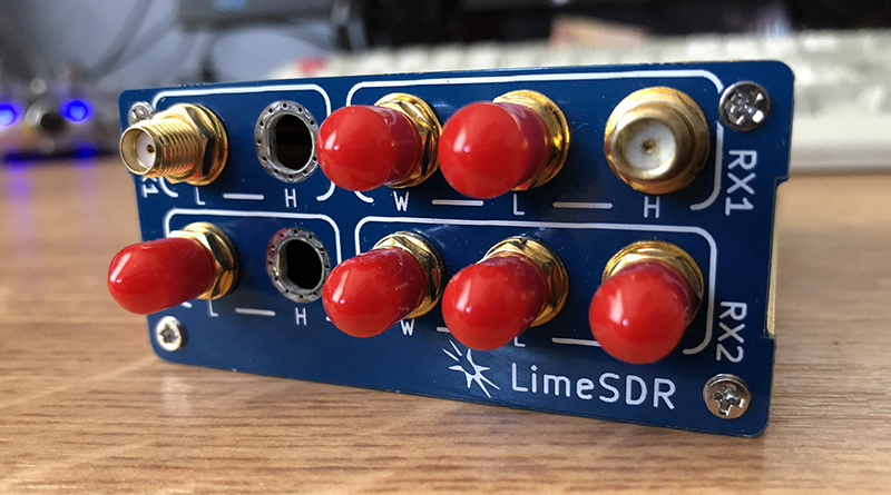
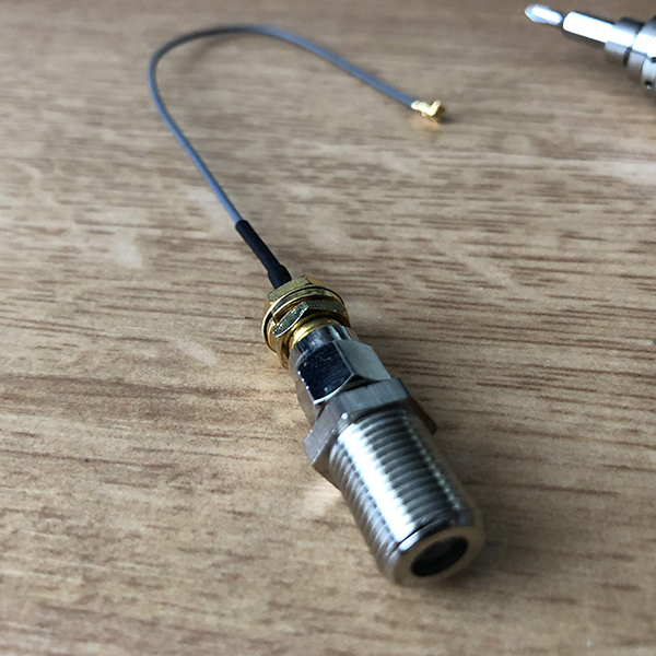 The correct way to do this would be to use a standard DOCSIS modem and become your own cable Internet provider. The equipment to do this is expensive, and if you’re already considering running WiFI over coax, you’re too deep down the rabbit hole to spend real money. Instead, [Manawyrm] simply made a few u.FL to F-connector adapters from u.FL to SMA, then SMA to F-connector adapters.
There are some problems with this plan. WiFi is 50 Ohms, TV coax cable is 75 Ohms. Only one MIMO channel will be available meaning the maximum theoretical bandwidth will be 433 Mbps. WiFi is also at much higher frequencies than what coax is designed for.
With two WiFi antenna to coax adapters, [Manawyrm] simply connected the coax directly to a router set up to bridge Ethernet over WiFi. The entire thing worked, although testing showed it was only getting about 60 Mbps of throughput. That’s not bad for something that was cobbled together out of old parts and unused wiring. Is it surprising that this worked? No, not really, but you’ve probably never seen anyone actually do it. Here’s the proof it does work, and if you’re ever in a bind, this is how you make WiFi wired.


Also, see an earlier (and more in-detail) writeup of a very similar setup: https://web.archive.org/web/20170421013902/http://wifiovercoax.mcleodnet.com/
My question now though, i how do you do this *properly?*
ummm, by using a proper networking solution?
<100m – ethernet over metal cables
100-150m – if it's not critical, ethernet, that 100m limit is a standard, not a brick wall ;-)
more – optical fiber
If you rent the splicer and do it yourself, it's no more expensive then CAT6 metal cabling…
A pair or 20.00 moca adapters and you are good to go. Ethernet in and out coax in between. 1ghz speed full duplex.
This. MOCA is specifically designed for this function, and it’s dirt cheap. I’ve used it in a stadium to deliver ethernet over old crappy RG-58. Works great, even through splitters.
Yes, MOCA looks extremely interesting and useful for this application.
I had never heard of this standard and these devices don’t seem to be available anywhere here in Germany.
But I have found a source in the Netherlands and will import 2 such devices and have a play around with them.
Thanks for mentioning these.
I don’t think the $20 adapters will actually do a gigabit, although they will coexist with the Wifi over coax solution.
Here are the following budget friendly ways I can think of to operate a LAN over coax that will coexist with each other:
* 5GHz Wifi (5 80MHz channels)
* 2.4GHz Wifi (3 20MHz channels or one 40MHz channel and one 20MHz channel)
* MOCA – 1-1.5GHz
The above will coexist with cable/antenna TV and DOCSIS, with the exception that older MOCA adapters do not coexist with newer versions of DOCSIS.
* DECA – DirecTV’s version of MOCA that runs at 500-600MHz (will not coexist with DOCSIS and probably will not coexist with antenna TV)
* Homeplug adapters hacked to connect via coax using baluns (will not coexist with DOCSIS but might coexist with antenna TV – must use filters to prevent unintended emissions)
Homeplug adapters can also be hacked to run over phone line and will coexist with analog telephones, but not DSL.
Many years ago, I stayed at a hotel where the Wifi was provided by a little Cisco box slightly bigger than a portable hard drive that goes between the TV and coax cable. Not sure exactly how it works but it does have its own power supply and I suspect it’s just some RF frequency translation hardware, with the smarts in the central controller.
Actiontec as a cheap source of MOCA bridges.
5GHz will suffer attenuation greatly on “TV grade” coax.
True, the usable cable length is going to be shorter than the other solutions. Of which, maybe something worth looking into is running 5GHz Wifi using air ducts as waveguides?
I just installed three Motorola MOCA 1 GB adaptors in my house… I have a ton of coax to all the rooms but, unfortunately, no easy way to get cat 5/6 where I need them to go. So far it’s working great, faster than my wifi, and took some of the load off my wifi for the things I can’t hard-wire.
coax from satellite tv is rated up to 3GHz, I wonder if that could work better
The standard F connector is good for up to 2ghz (if properly wired and high quality connectors and coax is used)
using ideal QUAM that would be somewhere around 1gbs and ideal across 10 networks is 100mbs
but realistically with the impedance mismatch close to 50mbs so it looks like whatever he is using is quite close to realistic saturation
But i mean i have seen GB ethernet over 100 meters with proper cabling so im not sure how useful any of this really is
That’s a pretty slick idea, and I really like it. I’d never have considered doing this. The mismatch between 75 ohm and 50 ohms isn’t horrible, and in fact many hams use 75 ohm cable because it’s cheap and abundant.
Yes, they do – but they also use antenna tuners, transmatches and similar gear to adapt the 75 ohm impedance to the 50 ohm that their radio needs. That’s not what has been done here.
I used to use a 170ft run of 75 ohm coax on hf. The swr was 1:1 because the signal loss attenuated any reflected power. In the wifi band coax cable will be extremely lossy.
Depends on the coax though. RG59 gets really lossy on long runs, RG11 will be a third that.
There’s a standard called moca for sending data over residential coax lines. Not quite as hacky, but quite convenient.
Problem is finding it reasonably priced compared to anything else. Invested money in it and it couldn’t do a lot of nodes.
The problem may be too strong signal. Maybe try with a 30dB attenuator in series.
I think it’s more likely reflection from the impedance miss-match. I would try a 75 ohm to 50 ohm balun.
Just wondering if Tobias has asked those “amateur radio operators in the house” to look at his setup.
I do not know how big his building is, but if WiFi can bridge 20m of thin air then it can probably bridge more of that through some (decent) coax.
Another Idea:
How many walls would you be able to cross with 2 cantenna’s?
Some government 3 or 4 letter acronyms may not like this idea, but if it has a big vertical component (from the basement to the attic) I do not see a ral reason to worry.
Heh, I‘m the Ham myself and my neighbor is licensed, too.
Instead of trying to impedance match the cables I tried a length of 50 Ohm coax and it didn‘t work much better. I will try some attenuators next and see if that works any better.
Properly built wifi could maybe work, but I have really thick walls out of clay and some metal insulation stuff and it‘s not too nice for wifi.
Gods, why am I thinking of Videodrome now?
Radio waves don’t do well with metal, and a thin layer of aluminum foil will block it really really well.
Or just a resistive impedance match, losing a few dB is not an issue in this setup.
neat idea, great use of a limeSDR
but i have had plenty of stability issues with limeSDR over long term uninterrupted usage even with proper cooling for an experimental GOES receiver
but its so easy to restart it might not be a problem with proper hardware resetting
um, actually he used standard Wifi routers. The LimeSDR just gave up its UFL-SMA adapters so he did have to wait for $shippingCompany to bring him some. Would have been cool to try that.
Like he says, the reflections from the impedance mismatch is causing the modem to select a larger guard interval and use a smaller QAM constellation.
So why not try an off-the-shelf 75/50 ohm transformer, or maybe even just throw one together with passive parts. It seems it would improve the transfer rate dramatically ?
There is also the option of a coax matching stub to transform impedance
https://pa0fri.home.xs4all.nl/Ant/Eentwaalfde golf trafo/One-twelfth wave transformer.htm
Here using even a simple resistive voltage divider would be beneficial as impedance matching device, decreasing both reflections over the line and transmitted signal level hence the distortion at the receiver. A good quality RF attenuator (not needlessly high power) would also act as a pretty good impedance matcher itself, because at its output it would be really close to line impedance no matter the impedance of the transmitter/receiver, and the reflection at the receiving end is what disrupts the transmission the most.
“but there are amateur radio operators in the house, and they put out a bunch of interference and noise”. Sounds like the ones I know too!
I would rather bet that the reason for “interference and noise” is the crappy consumer gear that is not shielded and often lacks any filters for out of band strong signals.
Amateur radio operators (HAMs) are extremely careful to not cause interference outside of their allocated frequency bands because there are large fines for that and in the worst case they could even lose their license.
However, a crappy TV with no/poor bandpass filter and poor shielding will happily get overloaded with a nearby strong signal (even on a frequency outside of the TV bands) and boom – “bad HAM causing interference”. Despite the fact that the HAM is doing nothing wrong and the FCC/CE/etc. certifications require that the TV accepts the interference …
Put the blame where it belongs, shall we?
BTW, if you tell that amateur radio operator about the problem, I am pretty certain they will be happy to help solving it. It is often very simple – a small filter is all that is needed in most cases. See e.g. here:
https://rsgb.org/main/technical/emc/using-emc-filters-and-ferrites/
I think you missed that the comment you’re replying to is a light-hearted joke.
I think the article text is actually saying networking over power cables would radiate too much noise for the amateur operators’ liking, not that the amateurs were the source of the radiated noise.
You can get Ethernet to coax converter ICs. Check out the EQCO875SC-HS from Microchip!
Bear in mind that this connects the grounds of all the wifi devices, which may be electrically hazardous in subtle ways! It’s fine if you know what you’re doing, but consider what happens if fault current travels down the shield of a piece of micro-coax and ignites it…
This is where the isolation from a proper balun transformer would be doubly useful.
“Wifi is 50 Ohms”
Everyone with a smidge of RF smarts knows what you’re trying to say, but let us expand that to..
“The radio frequency stage of the wifi equipment in use expected an input/output impedance of 50 ohms at the antenna jack.”
For the benefit of those not totally familiar with radio. Also capable of miscomprehension because wifi is becoming a colloquial synonym for internet connectivity in general and it getting lodged in people’s head that the internet is 50 ohms.
That said, I’m wondering why a house full of hams couldn’t rig an impedance matching balun.
This, thank you. +1
I pretty solidly understand the impedance on coax, but completely lost when it said “wifi is 50 ohms” rolled it over I my pre-coffee head a few times to ‘wifi antennae must be 50 ohm.’ Good to get a clarification, not yet being well versed in RF.
“If it’s stupid and it works, then it’s not stupid.” Uh,,, NO, it’s probably still stupid!
These cable types are not rated at all for use above 1 GHz., and the impedance mismatch causes other issues. Just because something “seems” to work does not mean its not causing other problems. Like causing interference with your next door neighbors baby monitor or “I’ve fallen and can’t get up” devices for the elderly.
“Ethernet over power lines was an option, but there are amateur radio operators in the house, and they put out a bunch of interference and noise.” Manybe the ones from like 10 years ago, but nowadays this is just not the case. a TP-Link AV2000 2000Mbps Powerline Ethernet Bridge, or Comtrend G.hn 1200 Mbps Powerline Ethernet Bridge will be just fine for the Hammers.
I’m more shocked that the “amateur radio operators” didn’t have a fit knowing you were going this route mismatching things.
Ha, I’ve always resented the old “if it’s stupid and it works” saying. There are millions of things that work, yet are still stupid. Maybe something like starting a BBQ with dioxygen difluoride. Will it catch on fire? You betcha. Is it incredibly, insanely stupid? Oh, most certainly.
Not that I’m criticizing this particular project, I don’t have enough RF knowledge to do that. But even the saying about stupid things that work is itself something that works yet is still stupid. It convinces people, but it’s also completely wrong.
dioxygen difluoride…nah, intead of the summary name, use structural naming scheme – FOOF
It also represents the sound of the outcome when it comes into contact with…most things…
Depends upon the technology.
https://en.wikipedia.org/wiki/Power-line_communication#Broadband_over_power_line
“cable types are not rated at all for use above 1 GHz”
This is using high quality sattelite TV coax, not “regular” TV coax.
It’s highly shielded, recommended up to 3 GHz and the manufacturer states a 6 GHz attenuation figure in it’s datasheet.
Yes, the impedance mismatch, too high signal levels and missing electrical isolation between the devices is a problem. I’m going to address these issues in some further experimentation, some proper attenuators should do the trick for the most part (well except the isolation thing).
I own a pair of AV1200 TP-Link gear and tried some Devolo-gear from a friend, both still generate interference. The HomePlus AV2 standard states that TX power in the ham bands need to be at least 30dB less, but that doesn’t help me if these things are in the same room as the radio.
If you take some precautions the electrical isolation shouldn’t be a problem.
Just make sure the PSUs are properly isolating, replace them with older, linear non SMPS(Us) or put small proper isolation transformers on all PSUs.
Assuming none of the APs are actually using the PE (protected earth) from the mains wiring this should take care of the power side.
Using only unshielded (UTP) cat > 5e Ethernet cables or ones where you strip on plug and attach a new one without connecting the shield (thus making one-side-only-connected-shield-cables) to connect to the APs should isolate other networked devices from the WW-LAN (WiredWireless LAN). The twisted pairs them selves are connected to isolation-transformers on both sides anyway.
Depending on the physical size of the WW-LAN, the overall grounding of and inside the building and what else uses the coax cables, it may be prudent to invest in some overvoltage surpessors/arrestors with F-connectors (like AXING SZU 6-02) and proper earthing of the coax shield, too.
“a TP-Link AV2000 2000Mbps Powerline Ethernet Bridge, or Comtrend G.hn 1200 Mbps Powerline Ethernet Bridge will be just fine for the Hammers” Last year I have do a EMC test of a product integrating a such modem. It showed very width modulated frequency band with a lot of energy far above any acceptable level. Reducing the multiples modulations slots to the industrial conformance level trashed to transmission capability to just a few Mbps. This things radiate a lot because the power lines are just copper wires never designed to carry RF frequencies. Still an acceptable solution in a lot of residential situations, but sometime it just hurt to much.
This (and moca) sound interesting. I have a WiFi proof house due to got air heating ducts. It would be tricky to run CAT6 in places but a previous owner “future proofed” it by running coax everywhere for TV.
Some people would describe that as a house fitted with waveguides ;-)
Now that would be a solution worth talking about!
I’m disappointed that the sdr is only used for it’s pigtails.
My biggest problem with this, is that it defeats a safety built into wired ethernet via transformers, and wifi via air-gap.
Galvanic isolation.. I think the last place I want to see a GND difference that can sink current is in my wifi antenna’s ground.
That router’s ground is now being dragged around by it’s coax ground, the only reason it’s ‘safe’ is because it has an isolation transformer on it’s DC input and the already mentioned ethernet transformers as well. So it’s effectively isolated to that single point for the moment.
MOCA is cheap and you can find adapters on Amazon easily. The only thing you have to do if put a filter on the head end entry point for the cable into the house to make sure the MOCA adapters signal doesnt bleed out into the neighborhood.
Gross losses due to Impedance Mismatch? Pffft!
Anyone who’s already chimed in so far, (and been dumb enough to also state that they additionally hold a Ham Ticket), should immediately surrender said Ticket and hang their head in shame!
When you ‘couple’ a 50ohm source to a 75ohm load, you’ll only have a minuscule VSWR mismatch of 1:1.5 to contend with.
Meaning that at worst case, a successful transfer of around 95% of the RF energy will occur at each point of mismatch, with about a 5% reflection of the RF back to its point of origin.
With this mismatch occurring twice, (once at each end), the total worst case theoretical loss across a pair of said mismatches, (by assuming a zero feedline loss between each mismatch), weighs in at just under 10%.
(5% of loss across the first mismatch, plus another 5% of loss from the remaining 95% of RF energy, as it crosses the second mismatch.)
Given that the TX PA found within the average Wi-Fi Access Point typically has to contend with substantially higher levels of VSWR, (when coupled to either their poorly designed factory supplied antennas, or antennas that are poorly placed up against other cables and/or metallic surfaces), all of this carry on about “Impedance Mismatch” sure does seem superfluous.
Another nails-on-chalkboard issue for me, is people who still insist on referring to plural antennas as “antennae”.
(Last time I checked, insects still don’t have much to do with RF, but I’m happy to hear from anyone concerning any new developments in this field…)
Again with the misdirected comments, surrounding “all of that attenuation” found on 75ohm Coax.
An utter Cane-Toad-load of RF is still going to arrive at the other end – even on RG59 – when compared to the brutal attenuation experienced by any RF signal traveling through free space.
My first suggestion to anyone attempting this would be to hope-and-pray that you’re lucky enough to be using RG59 as your transport medium to begin with, as this flavour of coax will already serve you around 20dB of attenuation per 30 feet, (at 2.5GHz.)
Depending on the sensitivity of the RF silicon at each end, you’re likely to damage each Wi-Fi Access Point due to front-end overload, without substantially limiting the RF signal to begin with.
Try first limiting the TX power of each Wi-Fi Access Point to the lowest possible setting – and if available from the internal settings or spec sheet, determining what this output level is, (in dBm.)
Most Wi-Fi devices will deliver you the highest level of MCS they are capable of delivering, one you achieve a minimum level of signal of at least say, around -50dBm of received signal strength.
Turning each device down from 17dBm, (typical for most devices, which is about 50mW of TX power), down to around only 0dBm, (which is only 1mW) – and then running a connection across 30 feet of RG59, will still result in an extremely strong -20dBm of signal!
(You could also confirm the received signal level within each device via its GUI, as confirmation that you’re not close to causing any damage…)
Even Wi-Fi on 5.8GHz is easily done, as RG59 will only attenuate a little over 30dB per 30 feet at this frequency – so have at it!
Remember, all you’re trying to do is land the RF arriving at the other end ‘light enough’ so as not to damage the receiving RF silicon, but still strong enough to allow the transceivers to negotiate the highest possible MCS that they are capable of.
A signal received at the far end that’s anywhere within -20dBm and -50dBm, will do you proud.
As for achieving 2×2, (or even 4×4), MIMO over a single run of Coax – that’s also trivial.
Reverse feed a pair of 75ohm 2-way splitters, (or a pair of 4-way splitters for 4×4 MIMO), at each end – fitted with individual 10dB attenuator pads on each port to prevent cross-port TX damage, and at one end, use dissimilar tail lengths out to each individual antenna port – just to introduce the required phase shift.
This stuff ain’t Rocket Sugery…
“Reverse feed a pair of 75ohm 2-way splitters, (or a pair of 4-way splitters for 4×4 MIMO), at each end – fitted with individual 10dB attenuator pads on each port to prevent cross-port TX damage, and at one end, use dissimilar tail lengths out to each individual antenna port – just to introduce the required phase shift.”
This sounds very interesting.
Could you elaborate a bit on the “and at one end, use dissimilar tail lengths out to each individual antenna port – just to introduce the required phase shift.” part?
I use 2 of Zyxel HLA3105 and works good over coax, i fund it on ebay for 30 USD each.
https://www.zyxel.com/us/en/products_services/hla3105.shtml?t=p
Network standard:
HomePNA 3.1
ITU-T G.9954
IEEE 802.3 Ethernet
IEEE 802.3u Fast Ethernet
IEEE 802.3x flow control
Range: up to 1,000 meters (3280 feet) over coaxial cable
Nodes: allow up to 60 HomePNA adaptors to connect to the coaxial home network
QoS: support the guaranteed (parameterized) and prioritized QoS
Security: AES 128-bit based encryption
ToS, VLAN Tag pass through
Frequency band: 12-44 MHz
“If it’s stupid and it works, then it’s not stupid”
What an utterly daft thing to say. “Assume A. B. Therefore not A”.
Perhaps you were going for “if it looks stupid, but it works, then it’s not stupid”. Even then, as pointed out elsewhere, there are innumerable things that remain stupid despite ‘working’.
“If it’s stupid and it works, it’s still stupid and you’re lucky.”
Not really a hack as much as lack of awareness that it’s already a thing. WiFi over coax has been used in Chinese hotels for years, and there are lots of WiFi/TV splitters for sale on taobao.com to the domestic Chinese market. Also looks like coaxifi.com sells 4 outlet kits that use pigtail splitter cables with custom F-connector antennas that thread over cable wall plates. (But why market the inexpensive stuff if some rube in the US is willing to spend $400 for meshed range extenders?)
A few notes about RG-6. The GHz rating on the coax shouldn’t be interpreted as some sort of stopband above which frequencies are cut off, but rather it’s just the highest frequency the manufacturer tested. You can use it for 20 GHz over short runs if you want. Times Microwave has a useful calculator on its site to estimate dB of signal loss. Use LMR-240 and up if you need extra range over 50 ohm assemblies. For 75 ohm, RG-6 is probably the best you can purchase from hardware stores, but the cablecos would use QR-320 for a better attenuation profile.
It is a hack. It works. Made me think. It is interesting and can be made safer: https://www.coaxifi.com/shop
Would this work with T pieces and multiple stations ?
If your using proper -3dB power splitters instead of literal t-pieces, yes!
I think this might be experiment worthy.
I often have to demo wifi only kit at trade events and with many hundred other AP’s in the area things get swamped.
Static demos, so fudge could be allowed for the sake of the environment without anyone the wiser.
Curious solution to the problem of networking to difficult to reach areas. You mentioned in your article that the data transmission speed wasn’t very significant. Perhaps (although I am unsure as to how well this work, its’ range etc) instead of using traditional WiFi with access points, you could try using IrDA (or a variation of Infrared) or perhaps Bluetooth (although I have never seen this implemented) instead.
The reason I suggest Infra-red over coax is I know it can be implemented for remotes, a lot of the parts I think already exist, USB to Infrared adaptors are available (unsure if these can both send and receive) and it can operate up to 1 Gbit/s (I think).
Please tell me if these are suitable suggestions or are nothing but a pipe dream.
10Base-2 (coax) -> 10Base-T (twisted pair) -> 802.11 over Coax (coax).
Nice fabrication with what you had on hand. I am a new techy trying to learn as much as possible from minds like yours. If someone set something up in a very similar manner in my home and the other end of the ethernet was a direct hook to an xbox one that he has using wifi and ethernet to complete connection, what has he done that causes no digital tv channels, no 5ghz option, a 5ghz light out from that strobes each sec(creepily reminds me of a very small scale emp) and unless Im seeing an overlay… we hook up to a bluetooth LAN and not our paid for xfinity service. I believe he is able to monitor us with it as well. I appreciate any help you could give. Trena
“Interesting read on the concept of ‘Wired Wireless over Coax.’ This innovative approach to combining the reliability of wired connections with the flexibility of wireless technology is intriguing. It seems like a promising solution for certain scenarios. Thanks for shedding light on this technology!”
“Exciting to see the innovation in wired wireless over coax technology! This could revolutionize how we set up surveillance systems, offering both reliability and flexibility. Looking forward to learning more about its applications and benefits.”